H
1
2
3
original.pdf layout_review.html excluded_blocks.html final_body_blocks.tsv layout_blocks.tsv
绿色编号 = 最终进入正文的段落顺序;蓝色虚线 = section heading 边界。每个条目同时显示 Docling 页内原序、新页内顺序和识别栏位;排序只在同页内调整,不拆分文本块。
| # | page | Docling 页内原序 | 新页内顺序 | global layout order | zone | column | region | bbox | text |
|---|---|---|---|---|---|---|---|---|---|
| 1 | 1 | 18 | 19 | 18 | body_zone | column_1_of_2 | p1:body_region:0 | [37.59, 509.71, 253.44, 132.83] | Lithium ion batteries (LIBs) have been used in electric vehicles because of their high energy density, safety, and low price; however, these qualities need to be further enhanced to extend the maximum distance that electric vehicles can travel before needing to be recharged [1 -3]. Many novel and advanced types of cathode materials have been explored and had their potentials gauged to meet the requirements of a high cell energy density [4]. Lithium-rich layered oxide (LRM), xLi2MnO3 ⋅ (1-x)LiMO2 (M = Ni, Co, Mn) has attracted considerable attention as the most promising alternative for LIBs, due to its high reversible discharge capacity (over 250 mAh g 1 ) and high range of operating voltage (3.0 -4.8 V) [5 -8]. However, its application is limited by the poor cycling and rate performance of LRM, which leads to the destruction of the cathode material structure and an unstable |
| 2 | 1 | 22 | 25 | 24 | body_zone | column_2_of_2 | p1:body_region:1 | [306.59, 488.79, 125.16, 7.31] | electrode/electrolyte interface [9]. |
| 3 | 1 | 23 | 26 | 25 | body_zone | column_2_of_2 | p1:body_region:1 | [306.59, 499.22, 253.42, 143.32] | To overcome these problems, several approaches have been explored in the past decade, including doping and coating [10 -13]. Recently, a simple and economical strategy has been developed: the formation of a protective interphase on the cathode through the preferential oxidation of additives ( < 5 wt%) added to the electrolyte. These additives have a higher highest occupied molecular orbital than solvents. This ensures that the electrolyte decomposition products do not react with the protective cathode interphase, resulting in the maintenance of interface stability. A variety of electrolyte additives with different molecular structures have been proposed. Tris(trimethylsilyl)phosphate [14,15] has been used as a film-forming additive on lithium-rich cathode materials to improve the electrochemical performance. Tris(trimethylsilyl) borate forms a modified solid electrolyte interphase (CEI) on the cathode, which reduces the capacity fading of a Li[Li0.2Mn0.54Ni0.13Co0.13] |
| 4 | 2 | 3 | 3 | 28 | top_margin | column_1_of_2 | p2:body_region:0 | [37.59, 55.48, 253.45, 289.75] | O2/Li cell from 81% to 26% after 200 cycles [16]. Lan et al. reported [17] that the electrode capacity retention in an electrolyte without any additive was 40%, which is much lower than the 72% observed in an electrolyte with bis(trimethylsilyl)carbodiimide. The capacity retention of Li1.2Mn0.54Ni0.13Co0.13O2 cathodes was found to increase in an electrolyte with 1 wt% diphenyl disulfide [18]. After 150 cycles, the capacity fading of Li1.2Mn0.54Ni0.13Co0.13O2 was found to decrease from 27.4% in an electrolyte without any additive to 8.8% an electrolyte with 1% 1,3,6-hexanetricarbonitrile [19]. The cycling stability of Li1.2Mn0.525Ni0.175Co0.1O2 cathodes was improved by using 5 wt% di-(2, 2,2 trifluoroethyl) carbonate in the electrolyte, and as a result, the capacity fading decreased from 30% to 11% after 50 cycles [20]. Cha et al. [21] investigated Li-rich/graphite full cells with 1 wt% lithium difluoro (oxalate)borate (LiDFOB) in 1.3 M LiPF6 containing an EC:EMC:DMC electrolyte at a volume ratio of 3:4:3. LiDFOB optimizes the surface composition of both the graphite anode and Li-rich cathode. A stable CEI film was produced on the Li[Li0.2Mn0.56Ni0.16Co0.08]O2 electrode with the presence of the decomposition products of tri(hexafluoro-iso-propyl) phosphate (HFiP). The capacity loss for a Li[Li0.2Mn0.56Ni0.16Co0.08]O2 electrode in an electrolyte with 1% HFiP after 130 cycles was shown to be reduced from 35.5% to 26.7% [22]. Triphenyl phosphite (TPPi) was found to preferentially oxidize over the solvent at an oxidation potential of 4.2 V (vs. Li/Li + ), and the TPPi-derived layer can effectively inhibit electrolyte decomposition [23]. Tu et al. reported that TEP reacted with active oxygen and formed a protective layer that suppressed electrolyte decomposition and the structural destruction of the LRM [24]. Triethyl borate and tripropyl borate have been reported as electrolyte additives that improve the self-discharge property of LRM cathodes [25]. |
| 5 | 2 | 4 | 4 | 29 | body_zone | column_1_of_2 | p2:body_region:0 | [37.59, 348.41, 253.44, 90.99] | Some studies have reported that the improvement of the electrochemical behavior of NCM622-based cells and LNMO-based cells are a result of silicon-based electrolyte additives [26 -28]. In this paper, 1, 3-divinyltetramethyldisiloxane (DTMS) was used as an additive to enhance the electrochemical properties of a Li-rich layered oxide cathode (LRM). Results showed that 2 vol% DTMS effectivity decreased capacity loss of LRM/Li cell from 57.2% to 25%. The possible mechanism for this was investigated further though electrochemical and physical analyses. |
| 6 | 2 | 7 | 7 | 32 | body_zone | column_1_of_2 | p2:body_region:0 | [37.59, 494.97, 253.43, 101.48] | The LRM cathode was composed of 80 wt% LRM (LRM300, Ningbo Li-rich Battery Material Technology Co., Ltd., China), 10 wt% polyvinylidene fluoride (PVDF) binder, and 10 wt% acetylene black in N -methyl-2-pyrrolidone. The slurry was coated on Al foil, and then vacuum dried at 100 ◦ C for 12 h. The CR2025-cell was fabricated in an Arfilled glove box with a Li sheet as the anode and Celgard 2325 as the separator. The base (BE) electrolyte contained 1 M LiPF6 and included EC/EMC/DMC (1:1:1, in weight). DTMS (Aladdin Co., Ltd., China) was then added into the BE electrolyte. Electrolytes with 2 vol% DTMS were used (Supplementary Material. 1). |
| 7 | 2 | 8 | 8 | 33 | body_zone | column_1_of_2 | p2:body_region:0 | [37.59, 599.57, 253.44, 38.72] | A total of 1000 ppm of hydrofluoric acid (HF) was then added into the BE and BE + 2 vol%DTMS electrolytes to prepare HF-containing electrolytes using a 40 wt% HF aqueous solution [25]. All electrolytes were prepared in an Ar-filled glove box. |
| 8 | 2 | 10 | 10 | 35 | bottom_margin | column_1_of_2 | p2:body_region:0 | [37.59, 673.32, 253.45, 70.07] | The charge -discharge performance of the cells was evaluated using a computer-controlled test system (CT2001A, China). The LRM/Li cells were pre-cycled in the following schedule: 0.1C (1C = 300 mA g 1 ) for three cycles and 0.2C for three cycles at 25 ◦ C between 2.8 and 4.8 V. The LRM/Li cells were then operated for 100 cycles at 0.5C to analyze the cycling performance. The rate capability of the cells was evaluated at a 0.5-1-2-3-5C charge/discharge current. The electrochemical |
| 9 | 2 | 12 | 12 | 37 | front_matter | column_2_of_2 | p2:body_region:1 | [366.12, 65.88, 134.12, 16.16] | /Li) of EC, DMC, EMC, and DTMS. |
| 10 | 2 | 13 | 13 | 38 | front_matter | column_2_of_2 | p2:body_region:1 | [306.59, 153.91, 253.39, 28.23] | impedance spectroscopy (EIS) was employed in the frequency range of 10 5 to 0.1 Hz with an amplitude of 5 mV, using a frequency response analyzer (VSP, Bio-logic). |
| 11 | 2 | 15 | 15 | 40 | body_zone | column_2_of_2 | p2:body_region:1 | [306.6, 218.02, 253.4, 80.56] | To understand the influence of DTMS on the cycling performance of LRM/Li cells, scanning electron microscopy (SEM; S-4800, Hitachi), transmission electron microscopy (TEM; JEM-2010, JELO), XRD analysis (XRD; Bruker D8 ADVANCE) using Cu Ka radiation, X-ray photoelectron spectroscopy (XPS; ESCALAB 250Xi), and 19 F nuclear magnetic resonance ( 19 F NMR; AVANCE III 400 MHz) analyses were carried out. The cycled electrodes (LRM and Li) were disassembled, rinsed with dimethyl carbonate solvent, and dried under vacuum. |
| 12 | 2 | 17 | 17 | 42 | body_zone | column_2_of_2 | p2:body_region:1 | [306.6, 334.41, 253.4, 38.72] | The Gaussian 09 software package was used for theoretical calculations. The equilibrium structures were determined using the B3LYP/6311G(d,p) level [28]. The oxidation potential (Eox) was obtained as follows[28]: |
| 13 | 2 | 18 | 18 | 43 | body_zone | column_2_of_2 | p2:body_region:1 | [306.6, 380.54, 236.56, 9.34] | Eox (Li + /Li) = [G(M + ) - G(M)]/F - 1.4 V |
| 14 | 2 | 21 | 21 | 46 | body_zone | column_2_of_2 | p2:body_region:1 | [306.6, 460.54, 253.42, 166.47] | The as-calculated oxidation potential and Li + binding affinity (Eb) are often used to forecast the oxidation tendency of an additive on the cathode surface [29,30]. The film-forming electrolyte additives have a lower oxidation potential than the electrolyte solvents. Therefore, the additives dominate the composition of the CEI film on the cathode. Furthermore, a low value of Li + Eb is suitable for the enrichment of the additive on the cathode surface [29]. The calculated Eox values of the solvents and DTMS are listed in Table 1. As per the theoretical calculation results, DTMS (5.58 V) has a lower Eox than EC (7.11 V), DMC (7.00 V), and EMC (6.99 V), indicating that DTMS has a lower oxidation stability than the electrolyte solvents. The optimized structures and solvent-Li + and DTMS-Li + Eb values are seen in Fig. 1. The Eb value of DTMS is lower than those of solvents. This indicates that the interaction between DTMS and Li + is weaker, so DTMS can easily accumulate at the cathode surface. DTMS may thus form a protective film at the positive electrode, as per the theoretical calculation results. |
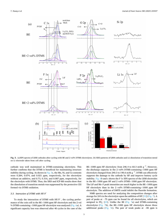
| 15 | 5 | 6 | 6 | 73 | bottom_margin | column_1_of_2 | p5:body_region:0 | [37.59, 704.67, 253.41, 38.72] | To study the interaction of DTMS with HF/F , the cycling performance of the coin cell in the BE + 1000 ppm HF electrolyte and the 2 vol % DTMS-containing + 1000 ppm HF electrolyte was analyzed (Fig. 6a). A significant capacity loss was observed after 40 cycles in the case of the |
| 16 | 5 | 7 | 7 | 74 | front_matter | column_2_of_2 | p5:body_region:1 | [306.59, 586.33, 253.42, 93.22] | BE + 1000 ppm HF electrolyte: from 246.4 to 60.3 mAh g 1 . However, the discharge capacity in the 2 vol% DTMS-containing + 1000 ppm HF electrolyte changed from 240.3 to 190.6 mAh g 1 . DTMS can effectively suppress the damage to the cathode by HF and improve battery cycle stability. Fig. 6b and c shows the F 1s XPS spectra of the LRM electrodes in the BE + 1000 ppm HF and 2 vol% DTMS + 1000 ppm HF electrolyte. The LiF and Me -F peak intensities are much higher in the BE + 1000 ppm HF electrolyte than in the 2 vol% DTMS-containing + 1000 ppm HF electrolyte. The addition of DMTS could inhibit the fluoride formation. |
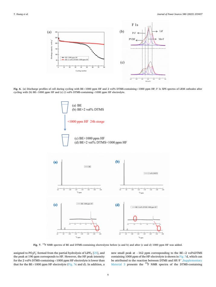
| 17 | 5 | 8 | 8 | 75 | bottom_margin | column_2_of_2 | p5:body_region:1 | [306.6, 682.73, 253.42, 59.58] | NMR spectra are used for analyzing the composition changes after storage for 24 h in the electrolyte upon the addition of HF [32] (Fig. 7). A pair of peaks at 75 ppm can be found for all electrolytes, which are assigned to PF6 [25]. Unlike the BE (Fig. 7a) and DTMS-containing electrolytes (Fig. 7b), the BE + 1000 ppm HF electrolyte shows three additional peaks (Fig. 7c). The pair of weak peaks at 85 ppm is |
| 18 | 6 | 4 | 4 | 80 | page_body | column_1_of_2 | [92.13, 673.38, 415.22, 8.36] | Fig. 7. 19 F NMR spectra of BE and DTMS-containing electrolytes before (a and b) and after (c and d) 1000 ppm HF was added. | |
| 19 | 6 | 5 | 5 | 81 | bottom_margin | column_1_of_2 | [37.59, 697.02, 253.41, 38.72] | assigned to PO2F2 formed from the partial hydrolysis of LiPF6 [25], and the peak at 190 ppm corresponds to HF. However, the HF peak intensity for the 2 vol% DTMS-containing + 1000 ppm HF electrolyte is lower than that for the BE + 1000 ppm HF electrolyte (Fig. 7c and d). In addition, a | |
| 20 | 6 | 6 | 6 | 82 | bottom_margin | column_2_of_2 | [306.59, 697.02, 253.42, 38.72] | new small peak at 162 ppm corresponding to the BE + 2 vol%DTMS containing 1000 ppm of the HF electrolyte is shown in Fig. 7d, which can be attributed to the reaction between DTMS and HF/F .Supplementary Material 3 presents the 19 F NMR spectra of the DTMS-containing | |
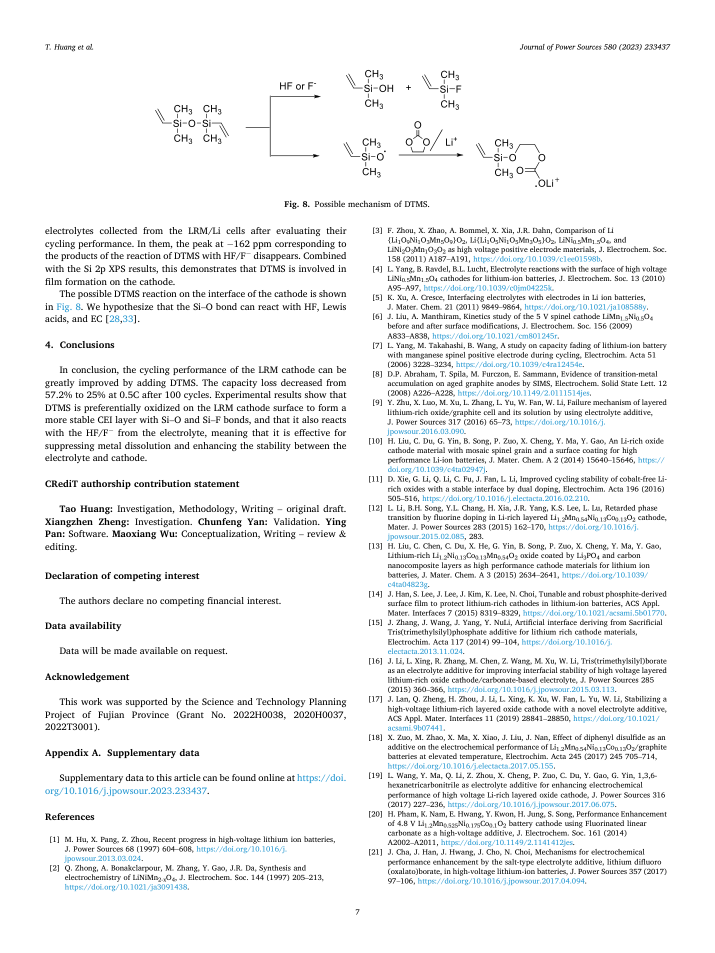
| 21 | 7 | 4 | 3 | 86 | front_matter | column_1_of_2 | p7:body_region:0 | [37.59, 189.96, 253.44, 49.15] | electrolytes collected from the LRM/Li cells after evaluating their cycling performance. In them, the peak at 162 ppm corresponding to the products of the reaction of DTMS with HF/F disappears. Combined with the Si 2p XPS results, this demonstrates that DTMS is involved in film formation on the cathode. |
| 22 | 7 | 6 | 4 | 87 | front_matter | column_1_of_2 | p7:body_region:0 | [37.59, 242.23, 253.43, 28.23] | The possible DTMS reaction on the interface of the cathode is shown in Fig. 8. We hypothesize that the Si -O bond can react with HF, Lewis acids, and EC [28,33]. |
| 23 | 7 | 8 | 6 | 89 | body_zone | column_1_of_2 | p7:body_region:0 | [37.59, 305.72, 253.42, 80.56] | In conclusion, the cycling performance of the LRM cathode can be greatly improved by adding DTMS. The capacity loss decreased from 57.2% to 25% at 0.5C after 100 cycles. Experimental results show that DTMS is preferentially oxidized on the LRM cathode surface to form a more stable CEI layer with Si -O and Si -F bonds, and that it also reacts with the HF/F from the electrolyte, meaning that it is effective for suppressing metal dissolution and enhancing the stability between the electrolyte and cathode. |