1
2
3
original.pdf layout_review.html excluded_blocks.html final_body_blocks.tsv layout_blocks.tsv
绿色编号 = 最终进入正文的段落顺序;蓝色虚线 = section heading 边界。每个条目同时显示 Docling 页内原序、新页内顺序和识别栏位;排序只在同页内调整,不拆分文本块。
| # | page | Docling 页内原序 | 新页内顺序 | global layout order | zone | column | region | bbox | text |
|---|---|---|---|---|---|---|---|---|---|
| 1 | 1 | 18 | 19 | 18 | page_body | left | [37.59, 453.09, 135.36, 35.32] | Atomic-scale HR-TEM analysis confirms that the engineered interface successfully mitigates rock-salt phase transitions. | |
| 2 | 1 | 19 | 20 | 19 | page_body | left | [37.59, 491.87, 135.37, 35.27] | The optimized surface architecture inhibits oxygen evolution and reduces manganese dissolution by more than 95%. | |
| 3 | 1 | 20 | 21 | 20 | page_body | left | [37.59, 530.65, 135.36, 25.69] | Enhanced interfacial kinetics enable a high-rate capacity of 130 mAh/g at 5C with 90.3% retention over 200 cycles. | |
| 4 | 2 | 6 | 8 | 38 | body_zone | column_1_of_3 | p2:body_region:0 | [37.59, 268.03, 253.44, 153.8] | The transition to a sustainable energy economy necessitates the development of next-generation energy storage technologies to meet the demands of transportation sector electrification and establish grid-scale energy storage solutions [1 -7]. Li-ion batteries (LIBs), which have dominated the portable electronics market for decades and represent the cornerstone of the electric vehicle (EV) industry, are at the forefront of this technological revolution [8 -12]. However, the ambitious targets set for long-range EVs and grid stabilization demand a transformative leap in battery performance, specifically energy density [13,14]. The cathode material is the primary determinant of LIB energy density and most important bottleneck impeding its increase. Conventional layered-oxide cathode materials, such as LiCoO2 and LiNi x Mn y Co2O2, have contributed to the rise of LIBs but feature specific capacities approaching theoretical maxima, which signals an urgent need for a shift to novel cathode chemistries to circumvent these limitations [15 -18]. |
| 5 | 2 | 7 | 9 | 39 | body_zone | column_1_of_3 | p2:body_region:0 | [37.59, 424.95, 253.43, 90.99] | Li-rich Mn-based layered oxides (LMRs) hold promise as nextgeneration cathode materials, delivering specific capacities ( > 250 mAh g 1 ) [19 -24] notably exceeding those of conventional materials (200 mAh g 1 ) by simultaneously harnessing the redox activity of transition metal (TM) cations and lattice oxygen anions (O 2 /O2 n ) [21, 23,24]. The activation of this anionic redox process typically occurs at a high-voltage plateau above 4.5 V vs. Li/Li + and unlocks substantial additional charge capacity [19,22] but triggers a cascade of severe degradation pathways, which hinder LMR commercialization [25,26]. |
| 6 | 2 | 8 | 10 | 40 | body_zone | column_1_of_3 | p2:body_region:0 | [37.59, 519.12, 253.44, 185.1] | One of the biggest challenges faced by LMRs is the severe continuous voltage fading during cycling, which leads to a rapid decrease in overall energy density and thereby negates the primary advantage of these cathode materials [27 -29]. This performance degradation is associated with the structural and interfacial instabilities of LMRs. The initial high-voltage activation triggers an irreversible migration of TM ions into vacancies within Li layers, initiating a gradual transformation from the desired layered framework to a disordered electrochemically inferior rock-salt phase at the particle surface [24,26,27]. Concurrently, the highly oxidized LMR surface becomes extremely reactive, engaging in parasitic reactions with the organic electrolyte [30] that lead to continuous electrolyte decomposition, TM (particularly Mn) dissolution into the electrolyte, and the formation of a thick ionically resistive cathode -electrolyte interphase (CEI) that stifles kinetics [31,32]. A direct consequence of this instability is the evolution of O2 from the LMR lattice, which can trigger violent exothermic reactions with the flammable electrolyte and thus poses thermal runaway and safety risks [31 -34]. |
| 7 | 2 | 9 | 11 | 41 | bottom_margin | column_1_of_3 | p2:body_region:0 | [37.59, 707.39, 253.44, 28.23] | Surface modification through the deposition of protective coatings is one of the most viable and effective strategies for confronting these multifaceted and interconnected failure modes [29,35,36]. A |
| 8 | 2 | 12 | 12 | 42 | body_zone | column_3_of_3 | p2:body_region:1 | [306.59, 247.11, 253.43, 70.07] | well-designed coating acts as a multifunctional shield passivating the reactive LMR surface and creating a robust physical and chemical barrier against the corrosive electrolyte. Among the potential coating materials, LiFePO4 (LFP) exhibits an advantageous property combination, namely high structural and thermal stability, environmental benignity, favorable kinetics as a Li-ion conductor, and robust P -O covalent bonds within its olivine structure [37 -41]. |
| 9 | 2 | 13 | 13 | 43 | body_zone | column_3_of_3 | p2:body_region:1 | [306.6, 320.35, 253.43, 153.75] | Herein, we examine the ability of a uniform nanoscale carbon-coated LFP (C-LFP) layer to function as a shield mitigating the primary degradation pathways in LMR cathodes. Unlike previous works employing conventional and often complex wet-chemical coating methods, we create a uniform and strongly adhered protective layer using a scalable, efficient, and solvent-free mechanofusion approach that is environmentally friendly and ideally suited for large-scale industrial production [42 -45]. When applied at an optimal loading of 0.75 wt%, the C-LFP coating suppresses the detrimental layered-to-rock-salt phase transition, accelerates Li-ion transport through the formation of a stable conductive interface, and stabilizes the cathode surface by preventing the critical release of lattice oxygen, thus dramatically enhancing electrochemical performance. This study provides a practical strategy for overcoming the long-standing challenges faced by LMR cathodes and unlocking their full potential for the next generation of high-energy LIBs. |
| 10 | 2 | 17 | 17 | 47 | body_zone | column_3_of_3 | p2:body_region:1 | [306.6, 540.04, 253.41, 122.34] | NiSO4 ⋅ 6H2O ( ≥ 99%, Sigma-Aldrich) and MnSO4 ⋅ H2O ( ≥ 98%, Sigma-Aldrich) were dissolved in deionized water to prepare a solution with a Mn:Ni molar ratio of 65:35 and total sulfate concentration of 2.0 M. This solution was fed into a continuously stirred tank reactor maintained at 60 ◦ C under nitrogen. Simultaneously, a 5.0 M aqueous NaOH ( ≥ 97%, Sigma-Aldrich) solution was added as a precipitant, and a 2.0 M aqueous NH3 (28% -30%, Sigma-Aldrich) solution was introduced as a chelating agent to control particle morphology. The stirring speed and pH of the reaction mixture were maintained at 10.8 ± 0.2 and 1000 rpm, respectively. After complete precipitation, the hydroxide precursor (Mn0.65Ni0.35(OH)2) was filtered, thoroughly washed with deionized water, and dried at 120 ◦ C for 24 h in a vacuum oven. |
| 11 | 2 | 18 | 18 | 48 | bottom_margin | column_3_of_3 | p2:body_region:1 | [306.6, 665.56, 253.42, 70.07] | The dried precursor was uniformly mixed with LiOH ⋅ H2O ( ≥ 98%, Sigma-Aldrich) at a Li:TM molar ratio of 1.4:1, and the mixture was calcined in a muffle furnace in air at 650 ◦ C for 4 h (heating rate: 2 ◦ C min 1 ) for decomposition and initial lithiation and then at 850 ◦ C for 12 h (heating rate: 2 ◦ C min 1 ) to form a well-crystallized layered structure. The furnace was naturally cooled to room temperature, and the resulting LMR powder (nominal composition: Li1.4Mn0.65Ni0.35O2) was collected |
| 12 | 3 | 3 | 3 | 52 | top_margin | column_1_of_2 | p3:body_region:0 | [37.59, 55.48, 83.95, 7.31] | and stored in dry room. |
| 13 | 3 | 5 | 5 | 54 | body_zone | column_1_of_2 | p3:body_region:0 | [37.59, 86.89, 253.43, 90.99] | Stoichiometric amounts of FeSO4 ⋅ 7H2O ( ≥ 99%, Sigma-Aldrich) and aqueous H2O2 (25 wt%) were introduced into a continuously stirred tank reactor. Subsequently, an aqueous NH4H2PO4 ( ≥ 98%, SigmaAldrich) solution was continuously fed into the reactor using a peristaltic pump while maintaining vigorous stirring at 1000 rpm at ambient temperature. The Fe:P molar ratio was controlled at 1:1 throughout the coprecipitation process. After complete precipitation, the FePO4 precursor was filtered, thoroughly washed with deionized water, and dried in an oven at 90 ◦ C for 24 h. |
| 14 | 3 | 6 | 6 | 55 | body_zone | column_1_of_2 | p3:body_region:0 | [37.59, 181.0, 253.44, 80.56] | The dried FePO4 precursor was mixed with Li2CO3 ( ≥ 99%, SigmaAldrich) and glucose ( ≥ 99%, Sigma-Aldrich) in deionized water under continuous stirring and heating. The Li:TM molar ratio was adjusted to 1.03:1 to ensure complete lithiation. The solvent was evaporated, and the obtained solid mixture was calcined at 800 ◦ C for 10 h in air (heating rate: 3 ◦ C min 1 ) to yield C-LFP. The calcined product was crushed using a juice mixer to obtain primary particles with an average size of 200 -300 nm. |
| 15 | 3 | 8 | 8 | 57 | body_zone | column_1_of_2 | p3:body_region:0 | [37.59, 285.6, 253.44, 122.4] | A predetermined amount of C-LFP (0.50, 0.75, 1.00, or 2.00 wt% relative to LMR) was mixed with LMR powder (50 g) in the mechanofusion chamber, and the mixture was subjected to high-speed mechanical processing (KMTECH Co., DFC-03K) at a rotational speed of 2000 rpm for 5 min under ambient conditions. The mechanical forces generated by the rotating blades and chamber wall caused the dispersion, deagglomeration, and physical grafting of C-LFP nanoparticles onto the surface of the larger LMR secondary particles through particle -particle collisions and frictional forces (Fig. S1) [43,44]. The resulting samples (denoted as LMR@F x , where x is the C-LFP loading in wt%) were stored in a humidity- and temperature-controlled dry room prior to electrode fabrication. |
| 16 | 3 | 11 | 11 | 60 | body_zone | column_1_of_2 | p3:body_region:0 | [37.59, 453.64, 253.44, 174.67] | High-resolution X-ray diffraction (XRD) patterns were collected using a Rigaku SmartLab diffractometer with a Cu K α radiation source ( λ = 1.5406 Å) operating at 45 kV and 200 mA. Data were recorded in the 2 θ range of 10 -80 ◦ at a step size of 0.02 ◦ and scan rate of 2 ◦ min 1 . The morphologies and microstructures of pristine and coated LMR samples were examined using field-emission scanning electron microscopy (FESEM; Carl Zeiss, Gemini 560) at an accelerating voltage of 3 -5 kV. Elemental mapping and line scan analyses were performed using energydispersive X-ray spectroscopy (EDS; X-MaxN 80, Oxford Instruments) coupled with FE-SEM to confirm the distribution of the C-LFP coating on the LMR particle surface. High-resolution transmission electron microscopy (HRTEM) images and selected area electron diffraction patterns were obtained using a JEOL JEM-2100F microscope operated at 200 kV to investigate the crystal structure, coating morphology, and interfacial characteristics at the atomic scale. The corresponding samples were prepared by dispersing powdered specimens in ethanol, drop-casting onto a Cu grid with a holey carbon film, and drying under vacuum. |
| 17 | 3 | 13 | 13 | 62 | bottom_margin | column_1_of_2 | p3:body_region:0 | [37.59, 652.4, 253.45, 90.99] | LMR@F x was used as the active cathode material, carbon black (Ketjen black, EC-600JD, AkzoNobel Co.) and carbon nanotubes (CNTs, Sigma-Aldrich) as conductive additives, and a solution of polyvinylidenedifluoride (PVDF; Solef 6020 and 5130, Solvay) in N -methyl2-pyrrolidone as a binder. The CNT dispersion (5 wt%) and PVDF solutions (6 wt% for Solef 6020 and 8 wt% for Solef 5130) were used directly without further dilution. A preliminary dispersion was obtained by combining the CNT solution (20.9 g), Solef 6020 solution (27.8 g), Solef 5130 solution (4.2 g), and carbon black (0.45 g) in a planetary |
| 18 | 3 | 14 | 14 | 63 | top_margin | column_2_of_2 | p3:body_region:1 | [306.59, 55.49, 253.42, 132.82] | mixer (AR-100, Thinky Co.). Subsequently, LMR@F x was incorporated into this premix so that the final electrode formulation contained 96.5 wt% active material, 1.5 wt% carbon black, and 2.0 wt% binder. The mixture was further homogenized to obtain a slurry, which was cast onto 20 μ m -thick Al foil (current collector) using a doctor blade and dried at 120 ◦ C for 2 h. The dried cathode sheets were calendered using a roll-press machine for density adjustment and vacuum-dried at 120 ◦ C for 12 h, featuring an areal loading of 10 mg cm 2 corresponding to an areal capacity of ~2 mAh cm 2 . Li foil (300 μ m, Honjo Metal Co., Japan) was used as counter and reference electrodes. A 14 μ m -thick polyethylene membrane (SB16C, W-Scope) was used as a separator. A 1.15 M solution of LiPF6 in EC:DMC:DEC (2:4:4, v/v/v) with 1.0 wt% VC (Solbrain) was used as an electrolyte. |
| 19 | 3 | 15 | 15 | 64 | body_zone | column_2_of_2 | p3:body_region:1 | [306.6, 191.49, 253.4, 80.5] | Galvanostatic charge -discharge cycling was performed using a WBCS3000L battery testing system (WonATech Co.) at 28 ◦ C in the voltage range of 2.0 -4.7 V vs. Li/Li + . The cells were subjected to three initial cycles at 0.1C (1C = 250 mA g 1 ) to stabilize the electrode -electrolyte interface, and rate capability tests were then conducted at various C-rates (0.2C, 0.5C, 1C, 2C, and 3C) for five cycles each followed by a return to 0.5C to assess capacity retention. Long-term cycling stability was evaluated at 0.5C for 200 cycles after the initial three cycles. |
| 20 | 3 | 16 | 16 | 65 | body_zone | column_2_of_2 | p3:body_region:1 | [306.6, 275.17, 253.42, 70.07] | Electrochemical impedance spectroscopy measurements were performed using a Biologic VMP3 potentiostat in the frequency range of 10 mHz to 100 kHz at an alternating-current amplitude of 5 mV. Electrochemical impedance spectra were collected after the third initial cycle in the fully discharged state (2.0 V) and fitted using equivalent circuits (ECLab software) to extract charge transfer resistance ( R ct) and other parameters. |
| 21 | 3 | 17 | 17 | 66 | body_zone | column_2_of_2 | p3:body_region:1 | [306.6, 348.42, 253.42, 59.58] | Li-ion diffusion coefficients ( D Li + values) during discharge were determined using galvanostatic intermittent titration technique (GITT) measurements. The cells were discharged at 0.1C for 30 min and allowed to relax for 2 h for the voltage to reach a quasi-equilibrium state. This process was repeated until the cell was fully discharged to 2.0 V. D Li + was calculated as |
| 22 | 3 | 18 | 18 | 67 | body_zone | column_2_of_2 | p3:body_region:1 | [306.6, 448.53, 253.41, 49.15] | where mB is the mass of the active material, VM is the molar volume of the active material, MB is the molar mass of the active material, S is the electrode -electrolyte contact area, Δ Es is the steady-state voltage change, Δ Et is the voltage change during the current pulse, and τ is the pulse duration. |
| 23 | 3 | 19 | 19 | 68 | body_zone | column_2_of_2 | p3:body_region:1 | [306.6, 500.86, 253.37, 17.74] | The volume resistivity of the cathode material was measured using an electrode resistance meter (Hioki RM2610). |
| 24 | 3 | 21 | 21 | 70 | body_zone | column_2_of_2 | p3:body_region:1 | [306.6, 542.7, 253.4, 59.64] | TM dissolution was quantified as follows. After 50 cycles at 0.5C, the cells were disassembled, and the cell components were rinsed with an identical volume of the electrolyte used in the cells (composition described above). The washings were collected using a syringe filter and analyzed by inductively coupled plasma mass spectrometry (Agilent 7700s) to determine the concentration of dissolved Mn. |
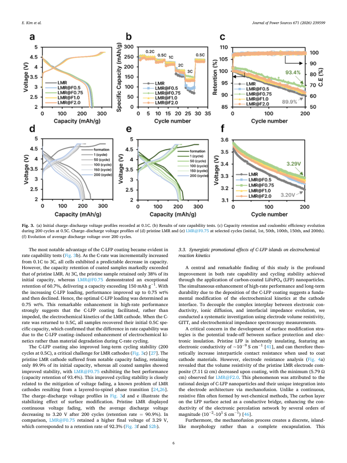
| 25 | 3 | 22 | 22 | 71 | body_zone | column_2_of_2 | p3:body_region:1 | [306.6, 605.46, 253.42, 80.56] | Differential scanning calorimetry (DSC, DSC204 F1 Phoenix, Netzsch) measurements were performed to evaluate the thermal stability of charged cathodes. Coin cells were charged to 4.8 V at 0.1C and then disassembled. The charged cathode material (~10 mg) was carefully scraped from the current collector, and a portion (0.75 mg) was sealed in a high-pressure stainless-steel pan together with fresh electrolyte (2.5 μ L). The sealed pan was heated from 25 ◦ C to 250 ◦ C at a rate of 5 ◦ C min 1 under nitrogen. |
| 26 | 3 | 23 | 23 | 72 | bottom_margin | column_2_of_2 | p3:body_region:1 | [306.6, 689.14, 253.43, 49.15] | The gas evolution in the cells was monitored and quantified by insitu differential electrochemical mass spectrometry (DEMS), which was constructed by a home-built design. The slurry of active material (LMR or LFP-coated LMR), Super P, and PVDF was coated on a SUS mesh and dried in an oven to be used as a working electrode. Lithium metal |
| 27 | 4 | 3 | 3 | 76 | top_margin | column_1_of_2 | p4:body_region:0 | [37.59, 55.48, 253.44, 174.67] | foil was used as a counter and reference electrode. Coin-type cells with a meshed top were assembled with the working electrode, the lithium electrode, and a glass microfiber membrane separator (GF/CTM, Whatman Co.) soaked with the electrolyte in a glove box. During in-situ DEMS analysis, galvanostatic charge-discharge cycling was performed on a potentiostat (BioLogic Science Instrument) at 0.1 C in the voltage range of 2.0-4.8 V vs. Li/Li + . The coin cell was placed in a cell holder attached with two capillaries for gas to flow in and out of the cell. The cell holder was integrated into the 2-position valve by connecting the two capillaries. During the cell was isolated for a programmed time (for example, 30 min), the gases evolved from the cell were accumulated in a headspace of the cell. When the 2-position valve was switched to another position, the gases were swept out of the cell by a carrier gas Ar. The mixed gases were transferred into a mass spectrometer (UGA-200, Stanford Research Systems), then the gases were identified by a mass-tocharge ratio ( m/z = 32 for O2 and 44 for CO2) and recorded as a partial pressure (Torr). |
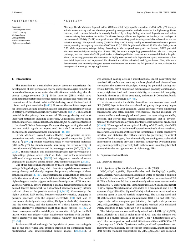
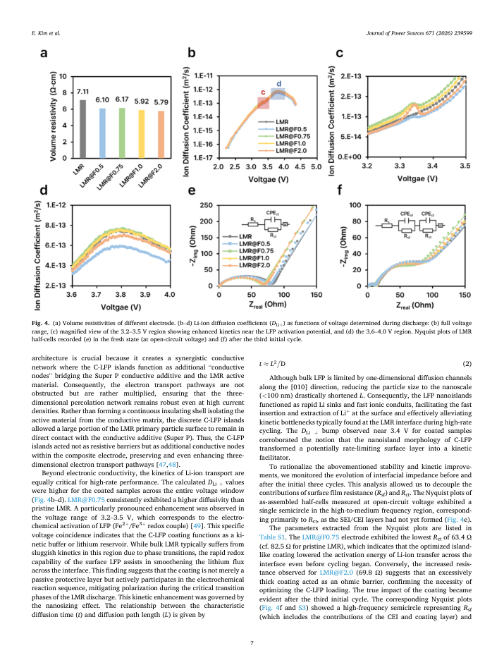
| 28 | 4 | 6 | 6 | 79 | body_zone | column_2_of_2 | p4:body_region:1 | [306.59, 97.33, 253.43, 153.75] | The core strategy of this work is to engineer a protective, ionically conductive, and electronically non-obstructive surface layer on Li- and Mn-rich (LMR) layered oxide cathodes to mitigate their intrinsic degradation pathways. To achieve this, we employed a scalable, solventfree mechanofusion (MF) process to coat LiFePO4 (LFP) nanoparticles onto the surface of secondary LMR particles (Fig. S1) [43,44]. The MF technique leverages high mechanical energy to disperse and graft nano-LFP particles onto the host LMR spheres, distinguishing it from conventional wet chemical coating or bulk coprecipitation methods. The conceptual difference between uncoated and coated LMR particles is illustrated in Fig. 1a. The uncoated LMR surface is susceptible to a cascade of detrimental reactions, including Mn leaching, lattice oxygen evolution, and irreversible structural transformation to a disordered rock-salt phase, which collectively cause severe performance degradation [31 -34]. The C-LFP coating was designed to act as a robust physical |
| 29 | 5 | 3 | 3 | 84 | top_margin | column_1_of_2 | p5:body_region:0 | [37.59, 55.48, 253.39, 17.8] | and chemical barrier passivating the reactive surface and preserving the structural integrity of the underlying layered framework. |
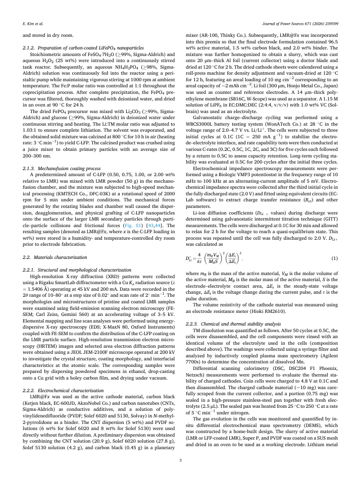
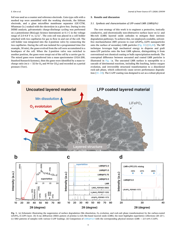
| 30 | 5 | 4 | 4 | 85 | front_matter | column_1_of_2 | p5:body_region:0 | [37.59, 76.4, 253.44, 165.31] | The effects of mechanofusion on bulk crystal structure were probed by XRD (Fig. 1b -d). The pattern of pristine LMR (Fig. 1b) exhibited the expected peaks, including the (003) and (104) peaks of the rhombohedral ( R 3 m ) phase and low-intensity superlattice peaks (inset; (020), (110)) at 2 θ = 20 -25 ◦ , confirming the presence of a monoclinic ( C 2/ m ) Li2MnO3-like component [28,32]. The patterns of LMR@F x (Fig. 1c) revealed the preservation of the bulk LMR structure, featuring no peaks of the olivine LFP phase even at the highest C-LFP loading. This absence does not indicate a failed coating process but rather reflects the low loading of C-LFP and, more importantly, its nanoscale particle size and potentially low crystallinity due to high-energy mechanofusion, which resulted in fine dispersion across the LMR surface rather than the formation of a separate bulk crystalline phase. When LMR was physically mixed with 2 wt% C-LFP without mechanofusion, distinct LFP peaks were observed, confirming the structural transformation of LFP induced by mechanofusion (Fig. 1d). |
| 31 | 5 | 5 | 5 | 86 | body_zone | column_1_of_2 | p5:body_region:0 | [37.59, 244.89, 253.44, 122.34] | The morphology of pristine and coated LMR particles was examined using FE-SEM (Fig. 2). The hydroxide precursor comprised spherical secondary particles (~5 μ m) composed of agglomerated plate-like primary particles (Fig. 2a). LMR retained this secondary particle morphology, featuring primary particles with sizes of ~200 nm (Fig. 2b). The overall spherical morphology of the secondary particles was perfectly preserved during mechanofusion (Fig. 2c -f), which resulted in surface decoration with C-LFP nanoparticles to create an island-like coating morphology. As the C-LFP loading increased to 2.0 wt % (LMR@F2.0, Fig. 2f), the surface coverage became more extensive, and the C-LFP nanoislands began to coalesce. Given the importance of preserving the underlying primary particle structure for retaining the |
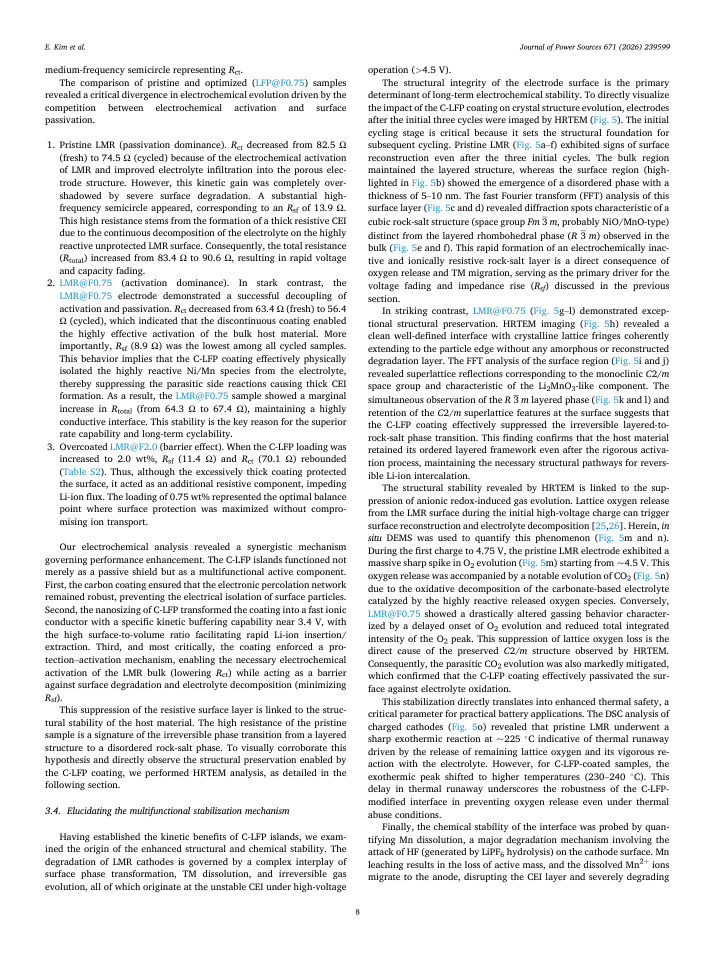
| 32 | 5 | 6 | 6 | 87 | top_margin | column_2_of_2 | p5:body_region:1 | [306.59, 55.49, 253.38, 17.8] | accessibility of the active-material bulk for lithiation/delithiation, these results demonstrate the need to control the C-LFP loading. |
| 33 | 5 | 7 | 7 | 88 | front_matter | column_2_of_2 | p5:body_region:1 | [306.59, 76.41, 253.41, 143.32] | The distribution of C-LFP was examined using EDS. Line scan analysis across a cross-sectioned LMR@F0.75 particle (Fig. 2g and h) revealed a uniform distribution of Mn and Ni. Importantly, Fe and P, the constituent elements of LFP, were detected primarily at the particle edges, which supported the presence of a surface-localized coating. This conclusion was corroborated by elemental mapping (Fig. 2i -l). The heterogeneous and punctate appearance of the elemental distribution maps suggests that C-LFP formed a discontinuous island-like morphology on the LMR surface rather than a continuous uniform thin film, with the density of these islands increasing with the C-LFP loading. This unique island-like architecture was paramount to electrochemical performance improvement, providing protection without completely isolating the active material from the ionic/conductive matrix, as elaborated in Section 3.3. |
| 34 | 5 | 9 | 9 | 90 | body_zone | column_2_of_2 | p5:body_region:1 | [306.59, 254.65, 253.43, 122.4] | The electrochemical performance of pristine and C-LFP-coated LMR cathodes was evaluated using coin-type half-cells. For all samples, the initial charge -discharge profiles recorded at 0.1C were characteristic of LMR cathodes, featuring a long plateau at ~4.5 V during the initial charge, which corresponds to the activation of Li2MnO3 and concurrent oxygen redox activity (Fig. 3a) [19,21]. Pristine LMR delivered a high initial discharge capacity of ~250 mAh g 1 [19]. All coated samples delivered comparable initial capacities, which indicated that the C-LFP coating was electrochemically active (as evidenced by the ~3.3 V plateau of LFP in Fig. S2a) and did not create notable inactive mass at these low loadings, hinder initial activation, or reduce the amount of LMR participating in the electrochemical reaction [37]. |
| 35 | 6 | 4 | 4 | 96 | body_zone | column_1_of_2 | p6:body_region:0 | [37.59, 425.18, 253.44, 164.24] | The most notable advantage of the C-LFP coating became evident in rate capability tests (Fig. 3b). As the C-rate was incrementally increased from 0.1C to 3C, all cells exhibited a predictable decrease in capacity. However, the capacity retention of coated samples markedly exceeded that of pristine LMR. At 3C, the pristine sample retained only 38% of its initial capacity, whereas LMR@F0.75 demonstrated an exceptional retention of 60.7%, delivering a capacity exceeding 150 mAh g 1 . With the increasing C-LFP loading, performance improved up to 0.75 wt% and then declined. Hence, the optimal C-LFP loading was determined as 0.75 wt%. This remarkable enhancement in high-rate performance strongly suggests that the C-LFP coating facilitated, rather than impeded, the electrochemical kinetics of the LMR cathode. When the Crate was returned to 0.5C, all samples recovered their initial 0.5C specific capacity, which confirmed that the difference in rate capability was due to the C-LFP coating -induced enhancement of electrochemical kinetics rather than material degradation during C-rate cycling. |
| 36 | 6 | 5 | 5 | 97 | bottom_margin | column_1_of_2 | p6:body_region:0 | [37.59, 592.53, 253.44, 143.32] | The C-LFP coating also improved long-term cycling stability (200 cycles at 0.5C), a critical challenge for LMR cathodes (Fig. 3c) [27]. The pristine LMR cathode suffered from notable capacity fading, retaining only 89.9% of its initial capacity, whereas all coated samples showed improved stability, with LMR@F0.75 exhibiting the best performance (capacity retention of 93.4%). This improved cycling stability is closely related to the mitigation of voltage fading, a known problem of LMR cathodes resulting from a layered-to-spinel phase transition [24,26]. The charge -discharge voltage profiles in Fig. 3d and e illustrate the stabilizing effect of surface modification. Pristine LMR displayed continuous voltage fading, with the average discharge voltage decreasing to 3.20 V after 200 cycles (retention rate = 90.9%). In comparison, LMR@F0.75 retained a higher final voltage of 3.29 V, which corresponded to a retention rate of 92.3% (Fig. 3f and S2b). |
| 37 | 6 | 7 | 7 | 99 | body_zone | column_2_of_2 | p6:body_region:1 | [306.59, 456.59, 253.42, 101.42] | A central and remarkable finding of this study is the profound improvement in both rate capability and cycling stability achieved through the application of carbon-coated LiFePO4 (LFP) nanoparticles. The simultaneous enhancement of high-rate performance and long-term durability due to the deposition of the C-LFP coating suggests a fundamental modification of the electrochemical kinetics at the cathode interface. To decouple the complex interplay between electronic conductivity, ionic diffusion, and interfacial impedance evolution, we conducted a systematic investigation using electrode volume resistivity, GITT, and electrochemical impedance spectroscopy measurements. |
| 38 | 6 | 8 | 8 | 100 | body_zone | column_2_of_2 | p6:body_region:1 | [306.6, 561.18, 253.41, 153.75] | A critical concern in the development of surface modification strategies is the potential trade-off between surface protection and electronic insulation. Pristine LFP is inherently insulating, featuring an electronic conductivity of ~10 9 S cm 1 [41], and can therefore theoretically increase interparticle contact resistance when used to coat cathode materials. However, electrode resistance analysis (Fig. 4a) revealed that the volume resistivity of the pristine LMR electrode composite (7.11 Ω cm) decreased upon coating, with the minimum (5.79 Ω cm) observed for LMR@F2.0. This phenomenon was attributed to the rational design of C-LFP nanoparticles and their unique integration into the electrode architecture via mechanofusion. Unlike a continuous, resistive film often formed by wet-chemical methods, The carbon layer on the LFP surface acted as a conductive bridge, enhancing the conductivity of the electronic percolation network by several orders of magnitude (10 2 -10 1 S cm 1 ) [46]. |
| 39 | 6 | 9 | 9 | 101 | bottom_margin | column_2_of_2 | p6:body_region:1 | [306.6, 718.05, 253.42, 17.8] | Furthermore, the mechanofusion process creates a discrete, islandlike morphology rather than a complete encapsulation. This |
| 40 | 7 | 4 | 4 | 106 | page_body | column_1_of_2 | p7:body_region:0 | [37.59, 420.42, 253.44, 132.83] | architecture is crucial because it creates a synergistic conductive network where the C-LFP islands function as additional ' conductive nodes ' bridging the Super P conductive additive and the LMR active material. Consequently, the electron transport pathways are not obstructed but are rather multiplied, ensuring that the threedimensional percolation network remains robust even at high current densities. Rather than forming a continuous insulating shell isolating the active material from the conductive matrix, the discrete C-LFP islands allowed a large portion of the LMR primary particle surface to remain in direct contact with the conductive additive (Super P). Thus, the C-LFP islands acted not as resistive barriers but as additional conductive nodes within the composite electrode, preserving and even enhancing threedimensional electron transport pathways [47,48]. |
| 41 | 7 | 5 | 5 | 107 | bottom_margin | column_1_of_2 | p7:body_region:0 | [37.59, 556.42, 253.45, 174.67] | Beyond electronic conductivity, the kinetics of Li-ion transport are equally critical for high-rate performance. The calculated D Li + values were higher for the coated samples across the entire voltage window (Fig. 4b -d). LMR@F0.75 consistently exhibited a higher diffusivity than pristine LMR. A particularly pronounced enhancement was observed in the voltage range of 3.2 -3.5 V, which corresponds to the electrochemical activation of LFP (Fe 2 + /Fe 3 + redox couple) [49]. This specific voltage coincidence indicates that the C-LFP coating functions as a kinetic buffer or lithium reservoir. While bulk LMR typically suffers from sluggish kinetics in this region due to phase transitions, the rapid redox capability of the surface LFP assists in smoothening the lithium flux across the interface. This finding suggests that the coating is not merely a passive protective layer but actively participates in the electrochemical reaction sequence, mitigating polarization during the critical transition phases of the LMR discharge. This kinetic enhancement was governed by the nanosizing effect. The relationship between the characteristic diffusion time ( t ) and diffusion path length ( L ) is given by |
| 42 | 7 | 6 | 6 | 108 | page_body | column_2_of_2 | p7:body_region:1 | [306.6, 443.89, 253.43, 101.48] | Although bulk LFP is limited by one-dimensional diffusion channels along the [010] direction, reducing the particle size to the nanoscale ( < 100 nm) drastically shortened L . Consequently, the LFP nanoislands functioned as rapid Li sinks and fast ionic conduits, facilitating the fast insertion and extraction of Li + at the surface and effectively alleviating kinetic bottlenecks typically found at the LMR interface during high-rate cycling. The D Li + bump observed near 3.4 V for coated samples corroborated the notion that the nanoisland morphology of C-LFP transformed a potentially rate-limiting surface layer into a kinetic facilitator. |
| 43 | 7 | 7 | 7 | 109 | page_body | column_2_of_2 | p7:body_region:1 | [306.6, 548.48, 253.4, 70.94] | To rationalize the abovementioned stability and kinetic improvements, we monitored the evolution of interfacial impedance before and after the initial three cycles. This analysis allowed us to decouple the contributions of surface film resistance ( R sf) and R ct. The Nyquist plots of as-assembled half-cells measured at open-circuit voltage exhibited a single semicircle in the high-to-medium frequency region, corresponding primarily to R ct, as the SEI/CEI layers had not yet formed (Fig. 4e). |
| 44 | 7 | 8 | 8 | 110 | bottom_margin | column_2_of_2 | p7:body_region:1 | [306.6, 621.73, 253.43, 111.91] | The parameters extracted from the Nyquist plots are listed in Table S1. The LMR@F0.75 electrode exhibited the lowest R ct of 63.4 Ω (cf. 82.5 Ω for pristine LMR), which indicates that the optimized islandlike coating lowered the activation energy of Li-ion transfer across the interface even before cycling began. Conversely, the increased resistance observed for LMR@F2.0 (69.8 Ω ) suggests that an excessively thick coating acted as an ohmic barrier, confirming the necessity of optimizing the C-LFP loading. The true impact of the coating became evident after the third initial cycle. The corresponding Nyquist plots (Fig. 4f and S3) showed a high-frequency semicircle representing R sf (which includes the contributions of the CEI and coating layer) and |
| 45 | 8 | 3 | 3 | 114 | top_margin | column_1_of_2 | p8:body_region:0 | [37.59, 55.48, 165.11, 8.18] | medium-frequency semicircle representing R ct . |
| 46 | 8 | 4 | 4 | 115 | front_matter | column_1_of_2 | p8:body_region:0 | [37.59, 65.97, 253.44, 38.66] | The comparison of pristine and optimized (LFP@F0.75) samples revealed a critical divergence in electrochemical evolution driven by the competition between electrochemical activation and surface passivation. |
| 47 | 8 | 5 | 5 | 116 | front_matter | column_1_of_2 | p8:body_region:0 | [39.23, 118.24, 251.79, 111.91] | Pristine LMR (passivation dominance). R ct decreased from 82.5 Ω (fresh) to 74.5 Ω (cycled) because of the electrochemical activation of LMR and improved electrolyte infiltration into the porous electrode structure. However, this kinetic gain was completely overshadowed by severe surface degradation. A substantial highfrequency semicircle appeared, corresponding to an R sf of 13.9 Ω . This high resistance stems from the formation of a thick resistive CEI due to the continuous decomposition of the electrolyte on the highly reactive unprotected LMR surface. Consequently, the total resistance ( R total) increased from 83.4 Ω to 90.6 Ω , resulting in rapid voltage and capacity fading. |
| 48 | 8 | 6 | 6 | 117 | front_matter | column_1_of_2 | p8:body_region:0 | [39.23, 233.33, 251.79, 132.83] | LMR@F0.75 (activation dominance). In stark contrast, the LMR@F0.75 electrode demonstrated a successful decoupling of activation and passivation. R ct decreased from 63.4 Ω (fresh) to 56.4 Ω (cycled), which indicated that the discontinuous coating enabled the highly effective activation of the bulk host material. More importantly, R sf (8.9 Ω ) was the lowest among all cycled samples. This behavior implies that the C-LFP coating effectively physically isolated the highly reactive Ni/Mn species from the electrolyte, thereby suppressing the parasitic side reactions causing thick CEI formation. As a result, the LMR@F0.75 sample showed a marginal increase in R total (from 64.3 Ω to 67.4 Ω ), maintaining a highly conductive interface. This stability is the key reason for the superior rate capability and long-term cyclability. |
| 49 | 8 | 7 | 7 | 118 | front_matter | column_1_of_2 | p8:body_region:0 | [39.23, 369.34, 251.79, 70.07] | Overcoated LMR@F2.0 (barrier effect). When the C-LFP loading was increased to 2.0 wt%, R sf (11.4 Ω ) and R ct (70.1 Ω ) rebounded (Table S2). Thus, although the excessively thick coating protected the surface, it acted as an additional resistive component, impeding Li-ion flux. The loading of 0.75 wt% represented the optimal balance point where surface protection was maximized without compromising ion transport. |
| 50 | 8 | 8 | 8 | 119 | front_matter | column_1_of_2 | p8:body_region:0 | [37.59, 453.01, 253.44, 133.64] | Our electrochemical analysis revealed a synergistic mechanism governing performance enhancement. The C-LFP islands functioned not merely as a passive shield but as a multifunctional active component. First, the carbon coating ensured that the electronic percolation network remained robust, preventing the electrical isolation of surface particles. Second, the nanosizing of C-LFP transformed the coating into a fast ionic conductor with a specific kinetic buffering capability near 3.4 V, with the high surface-to-volume ratio facilitating rapid Li-ion insertion/ extraction. Third, and most critically, the coating enforced a protection -activation mechanism, enabling the necessary electrochemical activation of the LMR bulk (lowering R ct) while acting as a barrier against surface degradation and electrolyte decomposition (minimizing R sf ). |
| 51 | 8 | 9 | 9 | 120 | front_matter | column_1_of_2 | p8:body_region:0 | [37.59, 588.96, 253.43, 70.07] | This suppression of the resistive surface layer is linked to the structural stability of the host material. The high resistance of the pristine sample is a signature of the irreversible phase transition from a layered structure to a disordered rock-salt phase. To visually corroborate this hypothesis and directly observe the structural preservation enabled by the C-LFP coating, we performed HRTEM analysis, as detailed in the following section. |
| 52 | 8 | 11 | 11 | 122 | bottom_margin | column_1_of_2 | p8:body_region:0 | [37.59, 694.24, 253.44, 49.15] | Having established the kinetic benefits of C-LFP islands, we examined the origin of the enhanced structural and chemical stability. The degradation of LMR cathodes is governed by a complex interplay of surface phase transformation, TM dissolution, and irreversible gas evolution, all of which originate at the unstable CEI under high-voltage |
| 53 | 8 | 12 | 12 | 123 | top_margin | column_2_of_2 | p8:body_region:1 | [306.59, 55.49, 69.5, 7.31] | operation ( > 4.5 V). |
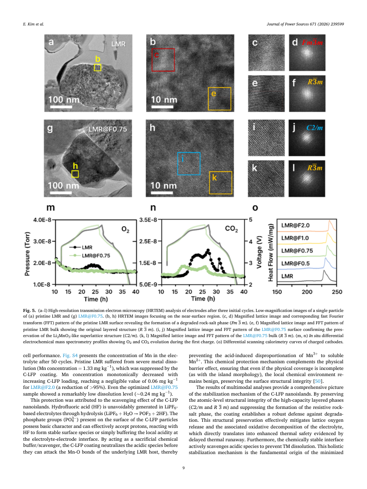
| 54 | 8 | 13 | 13 | 124 | front_matter | column_2_of_2 | p8:body_region:1 | [306.59, 65.98, 253.42, 187.31] | The structural integrity of the electrode surface is the primary determinant of long-term electrochemical stability. To directly visualize the impact of the C-LFP coating on crystal structure evolution, electrodes after the initial three cycles were imaged by HRTEM (Fig. 5). The initial cycling stage is critical because it sets the structural foundation for subsequent cycling. Pristine LMR (Fig. 5a -f) exhibited signs of surface reconstruction even after the three initial cycles. The bulk region maintained the layered structure, whereas the surface region (highlighted in Fig. 5b) showed the emergence of a disordered phase with a thickness of 5 -10 nm. The fast Fourier transform (FFT) analysis of this surface layer (Fig. 5c and d) revealed diffraction spots characteristic of a cubic rock-salt structure (space group Fm 3 m , probably NiO/MnO-type) distinct from the layered rhombohedral phase ( R 3 m ) observed in the bulk (Fig. 5e and f). This rapid formation of an electrochemically inactive and ionically resistive rock-salt layer is a direct consequence of oxygen release and TM migration, serving as the primary driver for the voltage fading and impedance rise ( Rsf ) discussed in the previous section. |
| 55 | 8 | 14 | 14 | 125 | front_matter | column_2_of_2 | p8:body_region:1 | [306.6, 256.4, 253.42, 144.39] | In striking contrast, LMR@F0.75 (Fig. 5g -l) demonstrated exceptional structural preservation. HRTEM imaging (Fig. 5h) revealed a clean well-defined interface with crystalline lattice fringes coherently extending to the particle edge without any amorphous or reconstructed degradation layer. The FFT analysis of the surface region (Fig. 5i and j) revealed superlattice reflections corresponding to the monoclinic C 2/ m space group and characteristic of the Li2MnO3-like component. The simultaneous observation of the R 3 m layered phase (Fig. 5k and l) and retention of the C 2/ m superlattice features at the surface suggests that the C-LFP coating effectively suppressed the irreversible layered-torock-salt phase transition. This finding confirms that the host material retained its ordered layered framework even after the rigorous activation process, maintaining the necessary structural pathways for reversible Li-ion intercalation. |
| 56 | 8 | 15 | 15 | 126 | front_matter | column_2_of_2 | p8:body_region:1 | [306.6, 403.97, 253.43, 174.67] | The structural stability revealed by HRTEM is linked to the suppression of anionic redox-induced gas evolution. Lattice oxygen release from the LMR surface during the initial high-voltage charge can trigger surface reconstruction and electrolyte decomposition [25,26]. Herein, in situ DEMS was used to quantify this phenomenon (Fig. 5m and n). During the first charge to 4.75 V, the pristine LMR electrode exhibited a massive sharp spike in O2 evolution (Fig. 5m) starting from ~4.5 V. This oxygen release was accompanied by a notable evolution of CO2 (Fig. 5n) due to the oxidative decomposition of the carbonate-based electrolyte catalyzed by the highly reactive released oxygen species. Conversely, LMR@F0.75 showed a drastically altered gassing behavior characterized by a delayed onset of O2 evolution and reduced total integrated intensity of the O2 peak. This suppression of lattice oxygen loss is the direct cause of the preserved C 2/ m structure observed by HRTEM. Consequently, the parasitic CO2 evolution was also markedly mitigated, which confirmed that the C-LFP coating effectively passivated the surface against electrolyte oxidation. |
| 57 | 8 | 16 | 16 | 127 | front_matter | column_2_of_2 | p8:body_region:1 | [306.6, 581.82, 253.4, 101.42] | This stabilization directly translates into enhanced thermal safety, a critical parameter for practical battery applications. The DSC analysis of charged cathodes (Fig. 5o) revealed that pristine LMR underwent a sharp exothermic reaction at ~225 ◦ C indicative of thermal runaway driven by the release of remaining lattice oxygen and its vigorous reaction with the electrolyte. However, for C-LFP-coated samples, the exothermic peak shifted to higher temperatures (230 -240 ◦ C). This delay in thermal runaway underscores the robustness of the C-LFPmodified interface in preventing oxygen release even under thermal abuse conditions. |
| 58 | 8 | 17 | 17 | 128 | bottom_margin | column_2_of_2 | p8:body_region:1 | [306.6, 686.42, 253.42, 49.15] | Finally, the chemical stability of the interface was probed by quantifying Mn dissolution, a major degradation mechanism involving the attack of HF (generated by LiPF6 hydrolysis) on the cathode surface. Mn leaching results in the loss of active mass, and the dissolved Mn 2 + ions migrate to the anode, disrupting the CEI layer and severely degrading |
| 59 | 9 | 4 | 4 | 133 | page_body | column_1_of_2 | p9:body_region:0 | [37.59, 574.34, 253.44, 70.07] | cell performance. Fig. S4 presents the concentration of Mn in the electrolyte after 50 cycles. Pristine LMR suffered from severe metal dissolution (Mn concentration = 1.33 mg kg 1 ), which was suppressed by the C-LFP coating. Mn concentration monotonically decreased with increasing C-LFP loading, reaching a negligible value of 0.06 mg kg 1 for LMR@F2.0 (a reduction of > 95%). Even the optimized LMR@F0.75 sample showed a remarkably low dissolution level (~0.24 mg kg 1 ). |
| 60 | 9 | 5 | 5 | 134 | bottom_margin | column_1_of_2 | p9:body_region:0 | [37.59, 647.53, 253.45, 91.05] | This protection was attributed to the scavenging effect of the C-LFP nanoislands. Hydrofluoric acid (HF) is unavoidably generated in LiPF6based electrolytes through hydrolysis (LiPF6 + H2O → POF3 + 2HF). The phosphate groups (PO4 3 ) present on the surface of the C-LFP particles possess basic character and can effectively accept protons, reacting with HF to form stable surface species or simply buffering the local acidity at the electrolyte-electrode interface. By acting as a sacrificial chemical buffer/scavenger, the C-LFP coating neutralizes the acidic species before they can attack the Mn-O bonds of the underlying LMR host, thereby |
| 61 | 9 | 6 | 6 | 135 | page_body | column_2_of_2 | p9:body_region:1 | [306.59, 572.1, 253.42, 51.38] | preventing the acid-induced disproportionation of Mn 3 + to soluble Mn 2 + . This chemical protection mechanism complements the physical barrier effect, ensuring that even if the physical coverage is incomplete (as with the island morphology), the local chemical environment remains benign, preserving the surface structural integrity [50]. |
| 62 | 9 | 7 | 7 | 136 | bottom_margin | column_2_of_2 | p9:body_region:1 | [306.6, 626.61, 253.43, 113.04] | The results of multimodal analyses provide a comprehensive picture of the stabilization mechanism of the C-LFP nanoislands. By preserving the atomic-level structural integrity of the high-capacity layered phases ( C 2/ m and R 3 m ) and suppressing the formation of the resistive rocksalt phase, the coating establishes a robust defense against degradation. This structural preservation effectively mitigates lattice oxygen release and the associated oxidative decomposition of the electrolyte, which directly translates into enhanced thermal safety evidenced by delayed thermal runaway. Furthermore, the chemically stable interface actively scavenges acidic species to prevent TM dissolution. This holistic stabilization mechanism is the fundamental origin of the minimized |
| 63 | 10 | 3 | 3 | 140 | top_margin | column_1_of_2 | p10:body_region:0 | [37.59, 55.48, 204.45, 7.31] | voltage fading and superior electrochemical performance. |
| 64 | 10 | 5 | 5 | 142 | body_zone | column_1_of_2 | p10:body_region:0 | [37.59, 97.66, 253.44, 80.5] | A highly effective and commercially viable strategy for overcoming the challenges hindering the commercialization of LMR cathodes was developed, corresponding to the deposition of a nanoisland-like C-LFP coating onto the surface of LMR secondary particles through a scalable solvent-free mechanofusion process. Multimodal analyses were performed to gain a comprehensive understanding of how rationally designed surface modification can unlock the full potential of LMR as high-energy cathode materials. |
| 65 | 10 | 6 | 6 | 143 | body_zone | column_1_of_2 | p10:body_region:0 | [37.59, 181.34, 253.45, 331.6] | At an optimized loading of only 0.75 wt%, C-LFP dramatically enhanced electrochemical performance, increasing capacity retention at 3C to > 60% and imparting superior long-term cycling stability (200 cycles) with notably suppressed voltage fading via synergistic mechanisms. The carbon coating provided enhanced electronic conductivity matching or exceeding that of the LMR substrate and thus ensured unimpeded electron transport. The C-LFP islands contributed to the overall electronic percolation network of the composite electrode. The discontinuous island-like morphology of the coating preserved direct electronic pathways between the active material (LMR) and conductive carbon, preventing disruptions in the conductive network of the electrode. Equally important is the role of nanosizing in enhancing Li-ion transport kinetics. The mechanofusion process reduced the C-LFP particle dimensions to the nanoscale, and the C-LFP nanoislands served as one-dimensional Li + conduction pathways, providing a kinetic boost that further enhanced rate performance. This effect was evidenced by the improved Li-ion diffusion coefficient observed using GITT measurements, particularly in the critical voltage region around 3.4 V. Instead of acting as a barrier, the nanoscale C-LFP coating facilitated rapid Li-ion transport and even provided additional electrochemically active sites for Li-ion insertion and extraction. Most importantly, this coating acted as a robust protective shield preventing the irreversible formation of a highly resistive and electrochemically inactive rock-salt phase on the LMR surface, which played a major role in maintaining low interfacial impedance and ensuring sustained high-rate performance during prolonged cycling. Furthermore, the protective C-LFP shield effectively passivated the reactive cathode surface, as evidenced by the drastic suppression of Mn dissolution ( > 95% reduction) and the evolution of the hazardous O2. HRTEM imaging confirmed that the CLFP coating successfully maintained the pristine layered structure on the particle surface, preventing the structural collapse plaguing unprotected LMR cathodes. |
| 66 | 10 | 7 | 7 | 144 | body_zone | column_1_of_2 | p10:body_region:0 | [37.59, 516.06, 253.44, 143.32] | This study not only presents a high-performance LMR cathode but also provides fundamental insights into the principles of designing surface coatings for next-generation battery materials. The mechanofusion-based approach using C-LFP nanoislands is a powerful, scalable, and cost-effective strategy that addresses the interconnected challenges pertaining to electronic conductivity, ionic transport, structural instability, and interfacial reactivity. The synergy between the carbon coating (responsible for electronic conductivity enhancement), nanosizing responsible for ionic conductivity), and island morphology (responsible for pathway preservation) represents a holistic design paradigm for advanced cathode materials. Thus, this work facilitates the realization of safe, stable, and ultrahigh-energy-density LIBs, accelerating their deployment in demanding applications such as long-range EVs and grid-scale energy storage. |