1
2
3
4
original.pdf layout_review.html excluded_blocks.html final_body_blocks.tsv layout_blocks.tsv
绿色编号 = 最终进入正文的段落顺序;蓝色虚线 = section heading 边界。每个条目同时显示 Docling 页内原序、新页内顺序和识别栏位;排序只在同页内调整,不拆分文本块。
| # | page | Docling 页内原序 | 新页内顺序 | global layout order | zone | column | region | bbox | text |
|---|---|---|---|---|---|---|---|---|---|
| 1 | 1 | 15 | 15 | 14 | page_body | column_1_of_2 | p1:body_region:0 | [69.45, 414.35, 237.05, 107.84] | ABSTRACT: Voltage and capacity fading of layer structured lithium and manganese rich (LMR) transition metal oxide is directly related to the structural and composition evolution of the material during the cycling of the battery. However, understanding such evolution at atomic level remains elusive. On the basis of atomic level structural imaging, elemental mapping of the pristine and cycled samples, and density functional theory calculations, it is found that accompanying the hoping of Li ions is the simultaneous migration of Ni ions toward the surface from the bulk lattice, leading to the gradual |
| 2 | 1 | 16 | 16 | 15 | page_body | column_1_of_2 | p1:body_region:0 | [69.45, 524.39, 486.04, 96.79] | depletion of Ni in the bulk lattice and thickening of a Ni enriched surface reconstruction layer (SRL). Furthermore, Ni and Mn also exhibit concentration partitions within the thin layer of SRL in the cycled samples where Ni is almost depleted at the very surface of the SRL, indicating the preferential dissolution of Ni ions in the electrolyte. Accompanying the elemental composition evolution, signi fi cant structural evolution is also observed and identi fi ed as a sequential phase transition of C 2/ m → I 41 → Spinel. For the fi rst time, it is found that the surface facet terminated with pure cation/anion is more stable than that with a mixture of cation and anion. These fi ndings fi rmly established how the elemental species in the lattice of LMR cathode transfer from the bulk lattice to surface layer and further into the electrolyte, clarifying the long-standing confusion and debate on the structure and chemistry of the surface layer and their correlation with the voltage fading and capacity decaying of LMR cathode. Therefore, this work provides critical insights for design of cathode materials with both high capacity and voltage stability during cycling. |
| 3 | 1 | 18 | 18 | 17 | bottom_margin | column_1_of_2 | p1:body_region:0 | [60.49, 660.42, 239.99, 96.94] | L ithium-ion batteries (LIBs) have been commercialized for more than two decades. Nowadays, driven by the demand of portable electronic device market, the next generation LIBs, featured with high capacity, high operating voltage, and high rate capability, are under intense investigations. 1 -6 In general, the cathode materials play a key role in determining the performance of LIBs. Thus, exploring and developing advanced cathode materials attracts more and more e ff orts around |
| 4 | 1 | 19 | 20 | 19 | page_body | column_2_of_2 | [324.45, 656.8, 240.01, 53.05] | world. 7 -9 To date, Mn-based LiNi x Mn1 -x -y Co y O2 (NCM), Nibased LiNi1 -x -y Co x Al y O2 (NCA), and Li -Mn-rich (LMR) cathode materials are among the most promising competitors in the cathode materials. 1,10 -16 However, commercialization of | |
| 5 | 2 | 3 | 2 | 29 | page_body | column_1_of_2 | p2:body_region:0 | [60.49, 69.37, 240.0, 229.79] | these cathode materials faces many challenges. For example, LMR cathode still su ff ered from voltage fading, capacity decay, cycling instability, and poor rate capability. Structurally, these three groups of cathode materials all exhibit a layered structure for pristine materials. 17 -20 After charge -discharge cycling, they all form a surface reconstruction layer (SRL), 20 -22 which have the following features: (1) formation of oxygen vacancies; (2) transition metal (TM) cations hopping into Li-sites; (3) TM cations being reduced to low valence state; and (4) lattice structure transformation. Obviously, the chemical and structural evolution of such a surface layer directly correlates to their electrochemical performance, which in essence has been attributed to one of the main causes for voltage fading, capacity decay, and cycling instability. In previous studies, several models have been proposed to interpret how the surface layer in fl uences electrochemical performance of the cathode materials. 21,23,24 Understanding of the structure, chemistry, and formation kinetics of the surface layer has been a hot topic in LIBs fi eld and considerable e ff orts have been used to probe the nature of the surface layer by utilizing a variety of experimental and computational approaches. 5,25 -31 |
| 6 | 2 | 4 | 3 | 30 | page_body | column_1_of_2 | p2:body_region:0 | [60.49, 301.36, 239.99, 251.9] | Although the common features of SRL have been well recognized as mentioned above, it is still far from clear on the fundamental mechanism behind the formation and evolution SRL during the cycling process. It has been reported that TM cations will hop into Li-sites both in TM-slab and Li-slab in the SRL; however, the dynamics and the kinetic mechanism of TM cation migration are still unclear. There are also debates on which TM cation hops into Li-sites. 5,18,21,31 -33 The role of oxygen vacancies in promoting surface reconstruction also needs further study. 3,26,34 Moreover, structural nature of the SRL is not clear, though rock salt, 5,20,35 disordered rock salt, 2 and spinel (including disordered-spinel/spinel-like) 10,21,23 structures have been used to describe the SRL structure. Compositionally, as compared with the bulk lattice, it is believed that the SRL is TM-rich and Li-poor, 21,22 but quantitative description of the SRL is not established yet. Additionally, it has been identi fi ed that Ni is prone to segregate to certain surface facets of particle even for the pristine LMR cathode particles. 28,36 The structure of such a pristine Nisegregation surface (PNS) layer is very similar to the cycling induced SRL. However, detailed comparison between cycling induced SRL and PNS layer is lacking, which makes it hard to distinguish PNS and SRL. |
| 7 | 2 | 5 | 4 | 31 | bottom_margin | column_1_of_2 | p2:body_region:0 | [60.49, 555.52, 240.0, 207.68] | In this work, using aberration-corrected scanning/transmission electron microscopes (S/TEM) equipped with high angle annular dark fi eld/annular bright fi eld (HAADF/ABF) detectors, advanced energy dispersive X-ray spectroscope (EDS) and electron energy loss spectroscope (EELS), we systematically studied the pristine and charge -discharge cycled Li 1.2Ni0.2Mn0.6O2 (LMR) cathode materials prepared by coprecipitation method. Combining atomic level structural imaging, quantitative high spatial chemical analysis and computational simulation and calculation, we captured unprecedented details on the formation, structure, and composition of SRL. For the fi rst time, we discovered that the formation of SRL layer is closely related to the hoping of Ni from TM layer to Li layer and subsequent migration of Ni from bulk lattice toward surface during the cyclic charge/discharge process, leading to the gradual depletion of Ni from the bulk lattice. The Ni and Mn ions at the very outer surface of the SRL show concentration partitions, with Ni almost being depleted at the very surface of the SRL, indicating preferential dissolution |
| 8 | 2 | 6 | 6 | 33 | page_body | column_2_of_2 | p2:body_region:1 | [324.45, 69.37, 240.04, 53.02] | of Ni ions in the electrolyte. Meanwhile, structural evolution is observed and identi fi ed as a sequential phase transition of C 2/ m → I 41 → spinel. The present work provides new insights as how structural and chemical evolutions of the SRL correlate with the voltage fading and capacity decaying of LMR cathode. |
| 9 | 2 | 7 | 7 | 34 | page_body | column_2_of_2 | p2:body_region:1 | [324.45, 124.59, 240.02, 274.02] | The LMR was synthesized by a coprecipitation process. Nickel sulfate hexahydrate (NiSO4 · 6H2O), manganese sulfate monohydrate (MnSO4 · H2O), sodium hydroxide (NaOH), and ammonium hydroxide (NH3 · H2O) were used as the starting materials to prepare Ni0.25Mn0.75(OH)2 precursor. The precursor material was washed with deionized water to remove residual sodium and sulfuric species, followed by fi ltering and drying. Afterward, Ni 0.25Mn0.75(OH)2 precursor was well mixed with Li 2 CO3 at a stoichiometric ratio for calcination (900 ° C for 14 h) to get the fi nal Li-excess cathode material. Coin cells were assembled with the as-prepared cathode materials, metallic lithium foil as counter electrode, Celgard K1640 monolayer polyethylene (PE) membrane as separator, and 1 M lithium hexa fl uorophosphate (LiPF 6 ) dissolved in ethyl carbonate (EC) and dimethyl carbonate (DMC) (1:2 in volume) as electrolyte in an argon- fi lled MBraun glovebox. Detailed experimental set up for cathode materials synthesis and electrochemical test can be found in our previous report. 37 The cathode samples were electrochemically tested by the following four methods: charged to 4.7 V (designated as 4.7 V sample); 5 cycles (5 cycled sample), 45 cycles (45 cycled sample) and 100 cycles (100 cycled sample). For the 4.7 V sample, the pristine sample was charged to 4.7 V at 0.1C rate. For the other three cells, they were cycled at a rate of 0.1C between 2.0 and 4.7 V vs Li/Li + at the room temperature. |
| 10 | 2 | 8 | 8 | 35 | page_body | column_2_of_2 | p2:body_region:1 | [324.45, 400.8, 240.03, 329.23] | Following the cycling of the battery, the obtained electrode was fi rst immersed in DMC for 12 h and then washed by DMC for three times and dried in vacuum for 12h. The electrode were peeled o ff from the Al-foil and grounded to fi ne powders. The powder particles were dusted on a lacy carbon TEM grid for microanalysis. Two probe aberration-corrected S/TEM microscopes were used for the microstructural study: FEI Titan 80-300 and JEOL JEM-ARM200CF. The SAED, HRTEM, STEM-HAADF observations and EELS analysis were conducted using Titan 80-300 microscope operated at 300 kV. HAADF images was collected by the annular detector in the range of 55 -220 mrad and EELS were acquired using Gatan Image Filter (GIF, Quantum 965) with collection semiangle ∼ 50 mrad. The electron beam has a convergence angle of 17.8 mrad. The STEM-HAADF/ABF imaging and EDS mapping were performed on JEOL JEM-ARM200CF microscope operated at 200 kV with a Schottky cold- fi eld emission gun. The HAADF and ABF pairs are simultaneously acquired with a beam convergence angle as 22 mrad. The HAADF and ABF images were acquired at 90 -370 mrad and 11 -22 mrad, respectively. The EDS elemental mapping was carried using the JEOL SDD- detector with a 100 mm 2 X-ray sensor, featuring a collection angle of ∼ 10 of traditional detector and, therefore, enabling high sensitivity and high performance analysis. The EELS data were collected from thin area to reduce multiple inelastic scatterings. A low-loss spectrum and the core-loss spectrum were collected from the same area at the same time. The low-loss spectrum was used to remove the multiple inelastic scattering e ff ect in the core-loss region using the Fourier ratio technique (DigitalMicrograph, Gatan Inc.). |
| 11 | 2 | 9 | 9 | 36 | bottom_margin | column_2_of_2 | p2:body_region:1 | [324.45, 732.28, 240.05, 30.91] | Computer simulations of electron di ff ractions and HRTEM images were conducted by using JEMS software. For di ff ractions, sample thickness is 60 nm. For HRTEM images, |
| 12 | 3 | 1 | 4 | 42 | page_body | column_1_of_2 | p3:body_region:0 | [60.49, 559.6, 240.01, 100.59] | the microscope parameters Cc and Cs are 1.2 mm and 0.7 mm, respectively. The STEM-HAADF simulations were conducted by the multislice method implanted in the Kirkland code. 38,39 For all the structures calculated in this work, the thickness of the supercells is set at 10 nm. The convergence angle and collection angles for the simulation is set in accordance with the experimental values. To incorporate thermal vibrations, four con fi gurations were averaged at 300 K with a probe fwhm 0.6 Å. |
| 13 | 3 | 5 | 5 | 43 | bottom_margin | column_1_of_2 | p3:body_region:0 | [60.49, 662.61, 240.01, 100.59] | Li2MnO3 and LiNi0.5Mn0.5O2 are two well-studied cathode materials. The former adopts monoclinic C 2/ m structure and the latter has an R 3 ̅ m layered structure. Because Li 1.2 Ni0.2Mn0.6O2 can be expressed as (50%Li2MnO3 + 50% LiNi0.5 Mn0.5O2), there has been a debate on the phase structure of LMR cathode. One is two-phase mixer structure. 27 The other is C 2/ m solid solution structure. 19,40 For the samples used in this work, high resolution X-ray powder di ff raction and intensive TEM observations reveals that the pristine LMR |
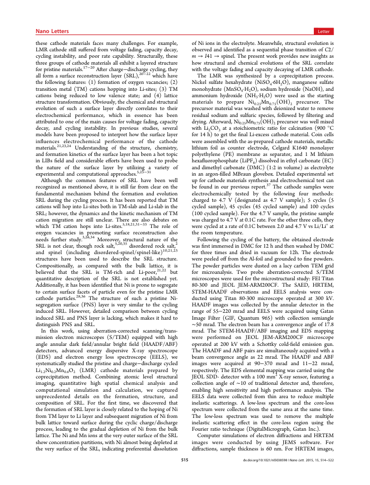
| 14 | 3 | 6 | 6 | 44 | bottom_margin | column_2_of_2 | p3:body_region:1 | [324.45, 559.06, 240.04, 204.14] | cathode particles exhibit a C 2/ m symmetry (see Figure S1 and S2 in the Supporting Information). Compared with ideal C 2/ m Li 2 MnO3 structure, due to more transition metal (TM) cations being incorporated, disordered TM-planes can be frequently seen in the pristine LMR structure (highlighted in Supporting Information Figure S2d). These disordered planes are due to a local TM segregation in the bulk material. It has been observed that Ni can segregate on particle surface to form a Ni-rich layer, 28 which can be called pristine Ni surface layer (PNS). As shown in Figure 1a and b, the current material also shows Nirich surface layer as evidenced by the bright contrast under STEM-HAADF imaging. The lattice structure of the Ni rich layer is di ff erent from the bulk lattice. Moreover, the surface (20 -2) planes show an ordered feature, which is evidenced by their intensity fl uctuation as marked by the white arrows in Figure 1b. Based on intensive observations, we found that the PNS layer only formed on the (20 -2) surface facets as evidenced by the additional STEM-HAADF images shown in |