正文阅读顺序审阅

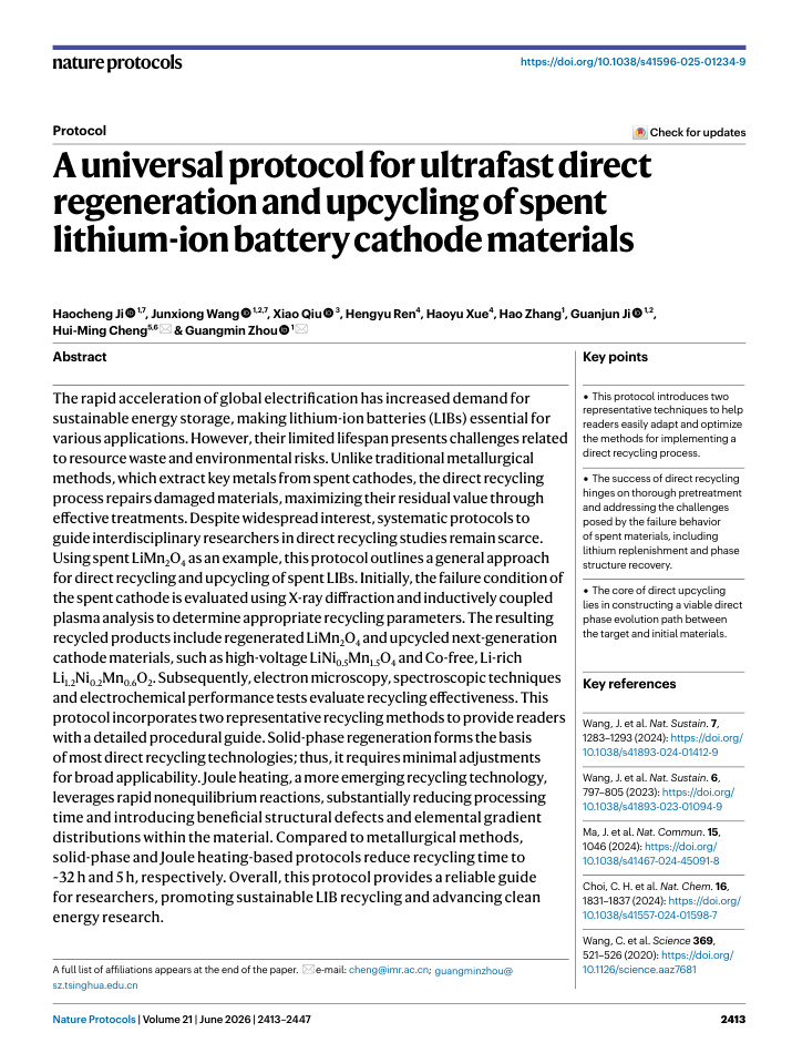
original.pdf layout_review.html excluded_blocks.html final_body_blocks.tsv layout_blocks.tsv

绿色编号 = 最终进入正文的段落顺序;蓝色虚线 = section heading 边界。每个条目同时显示 Docling 页内原序、新页内顺序和识别栏位;排序只在同页内调整,不拆分文本块。
页面叠框

Page 1

1
2
3
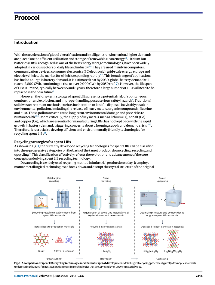
4
H
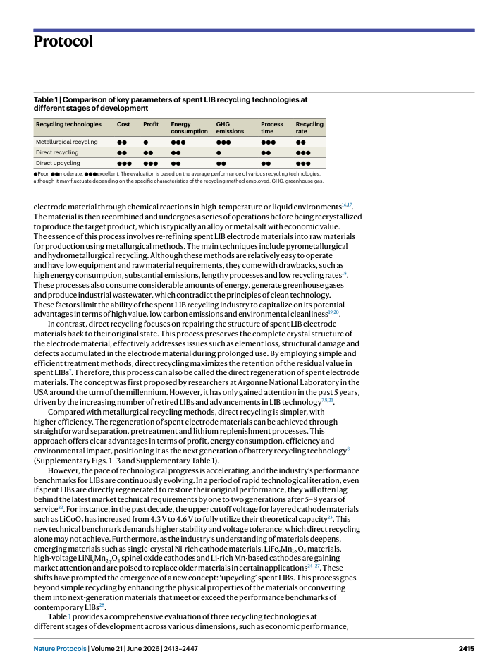
5

Page 2

H
H
6
7
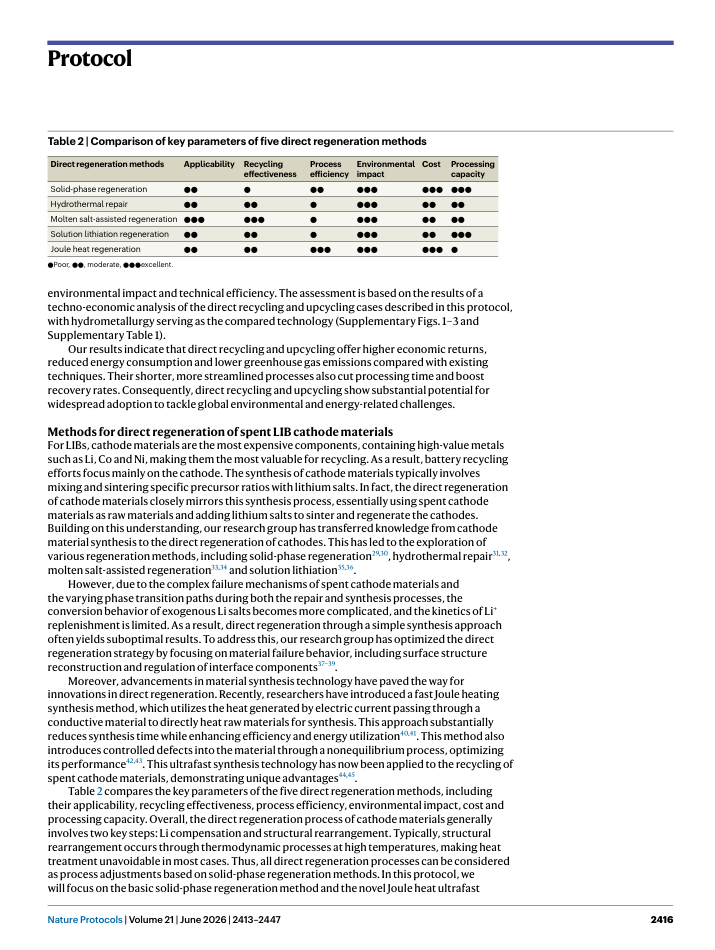
H
8
9

Page 3

H
10
11
12
13
14
15

Page 4

H
16
17
18
H
19
20
21
22

Page 5

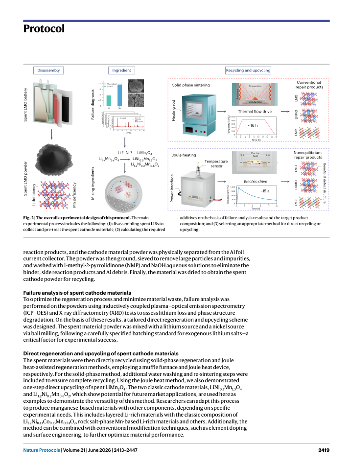
H
23
H
24
25
H
26

Page 6

H
H
27
28
29
30
31
32
33
34
H
35
36
37
38
H
39

Page 7

H
40
H
41
H
42

Page 8

H
H
43
H
44
H
45
46
47
48
49
50
H
51
H
H
52
53
54

Page 9

H
55
56
57
58
59
60
61
62
63
64
65
66
67
68
69
70
71
72
73
74
75
76
77
78

Page 10

H
79
80
81
82
83
84
85
86
H
87
88
89
90
91
92
93
94
95
96
97
98
99
100
101

Page 11

H
102
103
104
105
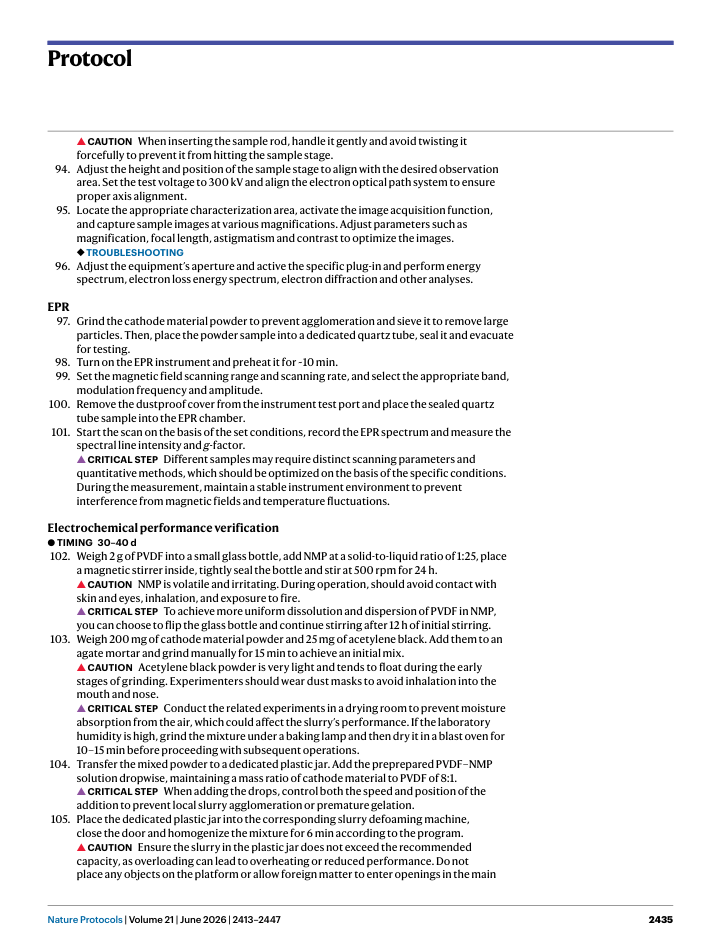
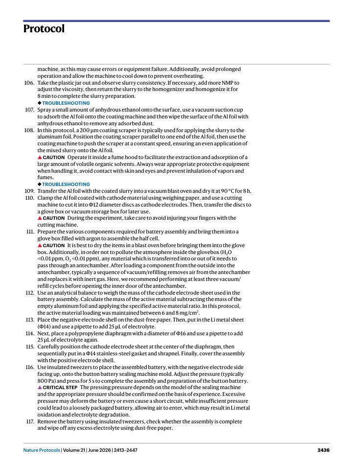
106
107
108
109
110
111
112
113
H
H
H
114
H
115
H
H
116
H
117
H
H
118

Page 12

H
119
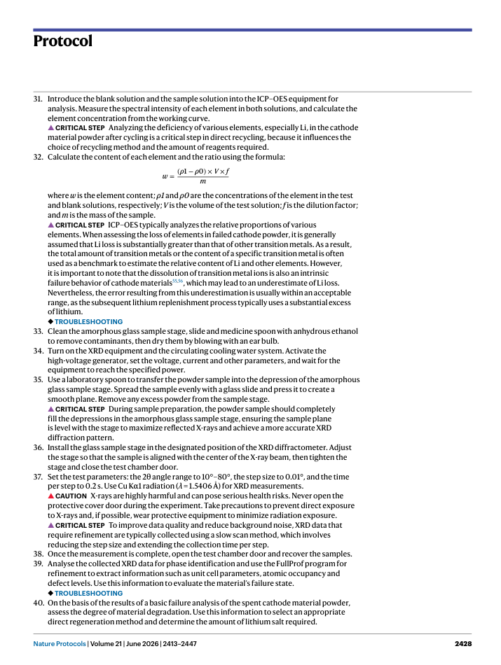
H
120
121
122
123
H
H
H
124
125
126
127
128

Page 13

H
129
130
131
132
133
134
135
136
137
138
139

Page 14

H
140
141
142
143
144
145
146
147
148
149
150
151
152
153
154
155
156
157

Page 15

H
158
H
H
159
160
161
162
163
164
165
166
167
168
169
170
171
172
173
174

Page 16

H
175
176
177
178
179
H
180
181
182
183
184
185
186
187
188
H
189

Page 17

H
190
H
H
191
H
192
193
194

Page 18

H
195
196
197
198
199
200
201
202
203
204
H
205
206
207
208
209

Page 19

H
210
211
212
213
214
215
216
H
217
218
219
220

Page 20

H
221
222
223
224
225
226
227
228
229
230
231
232
233
234
H
235

Page 21

H
236
237
H
238
239
H
240
241
H
H
242
243
244

Page 22

H
H
245
246
247
248
249
250
251
252
253
254
255
256
H
257
258
259
260
261
262
263

Page 23

H
264
265
266
267
H
268
269
270
271
272
273
H
274
275
276
277
278
279
280
281
282
283

Page 24

H
284
285
286
287
H
288
289
290
291
292
293
294
295
296
297

Page 25

H
298
299
300
301
302
303
304
H
305

Page 26

H
H
H
H
306

Page 27

H
307
308
309
310
H
311
312
313

Page 28

H
H
314
315
316
317
318
H
319
320
321
322
323
H
324
325
326
327
328
329
330

Page 29

H
H
331
H
332
333

Page 30

H
334
H
335

Page 31

H
336
H
337

Page 32

H
338
339

Page 33

H
340
H
341

连续正文顺序

#001 | page 1 | Docling页内原序 8 | 新页内顺序 9 | layout_order 8 | page_body / left_crossing | p1:body_region:0
The rapid acceleration of global electrification has increased demand for sustainable energy storage, making lithium-ion batteries (LIBs) essential for various applications. However, their limited lifespan presents challenges related to resource waste and environmental risks. Unlike traditional metallurgical methods, which extract key metals from spent cathodes, the direct recycling process repairs damaged materials, maximizing their residual value through effective treatments. Despite widespread interest, systematic protocols to guide interdisciplinary researchers in direct recycling studies remain scarce. Using spent LiMn 2 O4 as an example, this protocol outlines a general approach for direct recycling and upcycling of spent LIBs. Initially, the failure condition of the spent cathode is evaluated using X-ray diffraction and inductively coupled plasma analysis to determine appropriate recycling parameters. The resulting recycled products include regenerated LiMn 2 O4 and upcycled next-generation cathode materials, such as high-voltage LiNi 0.5 Mn1.5 O4 and Co-free, Li-rich Li 1.2 Ni0.2 Mn0.6 O2. Subsequently, electron microscopy, spectroscopic techniques and electrochemical performance tests evaluate recycling effectiveness. This protocol incorporates two representative recycling methods to provide readers with a detailed procedural guide. Solid-phase regeneration forms the basis of most direct recycling technologies; thus, it requires minimal adjustments for broad applicability. Joule heating, a more emerging recycling technology, leverages rapid nonequilibrium reactions, substantially reducing processing time and introducing beneficial structural defects and elemental gradient distributions within the material. Compared to metallurgical methods, solid-phase and Joule heating-based protocols reduce recycling time to ~32 h and 5 h, respectively. Overall, this protocol provides a reliable guide for researchers, promoting sustainable LIB recycling and advancing clean energy research.
#002 | page 1 | Docling页内原序 12 | 新页内顺序 10 | layout_order 9 | page_body / right |
This protocol introduces two representative techniques to help readers easily adapt and optimize the methods for implementing a direct recycling process.
#003 | page 1 | Docling页内原序 13 | 新页内顺序 11 | layout_order 10 | page_body / right |
The success of direct recycling hinges on thorough pretreatment and addressing the challenges posed by the failure behavior of spent materials, including lithium replenishment and phase structure recovery.
#004 | page 1 | Docling页内原序 14 | 新页内顺序 12 | layout_order 11 | page_body / right |
The core of direct upcycling lies in constructing a viable direct phase evolution path between the target and initial materials.
SECTION | page 1 | Docling页内原序 15 | 新页内顺序 15 | layout_order 14 | page_body / right |
Key references
#005 | page 1 | Docling页内原序 9 | 新页内顺序 18 | layout_order 17 | bottom_margin / left | p1:body_region:0
A full list of affiliations appears at the end of the paper.
SECTION | page 2 | Docling页内原序 1 | 新页内顺序 1 | layout_order 23 | top_margin / left | p2:body_region:0
Protocol
SECTION | page 2 | Docling页内原序 2 | 新页内顺序 2 | layout_order 24 | body_zone / left | p2:body_region:0
Introduction
#006 | page 2 | Docling页内原序 3 | 新页内顺序 3 | layout_order 25 | body_zone / left_crossing | p2:body_region:0
With the acceleration of global electrification and intelligent transformation, higher demands are placed on the efficient utilization and storage of renewable clean energy 1,2 . Lithium-ion batteries (LIBs), recognized as one of the best energy storage technologies, have been widely adopted in various sectors of daily life and industry 3,4 . They are used mainly in computers, communication devices, consumer electronics (3C electronic), grid-scale energy storage and electric vehicles, the market for which is expanding rapidly 5,6 . This broad range of applications has fueled a surge in battery demand. It is estimated that by 2030, global battery demand will reach ~2,800 GWh, continuing to rise to over 9,000 GWh by 2050 (ref. 7). However, the lifespan of LIBs is limited, typically between 5 and 8 years, therefore a large number of LIBs will need to be replaced in the near future 8 .
#007 | page 2 | Docling页内原序 4 | 新页内顺序 4 | layout_order 26 | body_zone / left_crossing | p2:body_region:0
However, the long-term storage of spent LIBs presents a potential risk of spontaneous combustion and explosion, and improper handling poses serious safety hazards 9 . Traditional solid waste treatment methods, such as incineration or landfill disposal, inevitably result in environmental pollution, including the release of heavy metals, organic compounds, fluorine and dust. These pollutants can cause long-term environmental damage and pose risks to human health 10,11 . More critically, the supply of key metals such as lithium (Li), cobalt (Co) and copper (Cu), which are essential for manufacturing LIBs, has not kept pace with the rapid growth in battery demand, triggering concerns about a looming supply and demand crisis 12,13 . Therefore, it is crucial to develop efficient and environmentally friendly technologies for recycling spent LIBs 14 .
SECTION | page 2 | Docling页内原序 5 | 新页内顺序 5 | layout_order 27 | body_zone / left | p2:body_region:0
Recycling strategies for spent LIBs
#008 | page 2 | Docling页内原序 6 | 新页内顺序 6 | layout_order 28 | body_zone / left_crossing | p2:body_region:0
As shown in Fig. 1, the currently developed recycling technologies for spent LIBs can be classified into three progressive categories on the basis of the target product: downcycling, recycling and upcycling 15 . This classification effectively reflects the evolution and advancement of the core concepts underlying spent LIB recycling technology.
#009 | page 2 | Docling页内原序 7 | 新页内顺序 7 | layout_order 29 | body_zone / left_crossing | p2:body_region:0
Downcycling is a widely used recycling method in industrial production today. It employs mature metallurgical technologies to break down and disrupt the crystal structure of the original
SECTION | page 3 | Docling页内原序 1 | 新页内顺序 1 | layout_order 69 | top_margin / left | p3:body_region:0
Protocol
#010 | page 3 | Docling页内原序 3 | 新页内顺序 3 | layout_order 71 | page_body / left_crossing | p3:body_region:0
● Poor, ●● moderate, ●●● excellent. The evaluation is based on the average performance of various recycling technologies, although it may fluctuate depending on the specific characteristics of the recycling method employed. GHG, greenhouse gas.
#011 | page 3 | Docling页内原序 4 | 新页内顺序 4 | layout_order 72 | page_body / left_crossing | p3:body_region:0
electrode material through chemical reactions in high-temperature or liquid environments 16,17 . The material is then recombined and undergoes a series of operations before being recrystallized to produce the target product, which is typically an alloy or metal salt with economic value. The essence of this process involves re-refining spent LIB electrode materials into raw materials for production using metallurgical methods. The main techniques include pyrometallurgical and hydrometallurgical recycling. Although these methods are relatively easy to operate and have low equipment and raw material requirements, they come with drawbacks, such as high energy consumption, substantial emissions, lengthy processes and low recycling rates 18 . These processes also consume considerable amounts of energy, generate greenhouse gases and produce industrial wastewater, which contradict the principles of clean technology. These factors limit the ability of the spent LIB recycling industry to capitalize on its potential advantages in terms of high value, low carbon emissions and environmental cleanliness 19,20 .
#012 | page 3 | Docling页内原序 5 | 新页内顺序 5 | layout_order 73 | page_body / left_crossing | p3:body_region:0
In contrast, direct recycling focuses on repairing the structure of spent LIB electrode materials back to their original state. This process preserves the complete crystal structure of the electrode material, effectively addresses issues such as element loss, structural damage and defects accumulated in the electrode material during prolonged use. By employing simple and efficient treatment methods, direct recycling maximizes the retention of the residual value in spent LIBs 7 . Therefore, this process can also be called the direct regeneration of spent electrode materials. The concept was first proposed by researchers at Argonne National Laboratory in the USA around the turn of the millennium. However, it has only gained attention in the past 5 years, driven by the increasing number of retired LIBs and advancements in LIB technology 7,8,21 .
#013 | page 3 | Docling页内原序 6 | 新页内顺序 6 | layout_order 74 | page_body / left_crossing | p3:body_region:0
Compared with metallurgical recycling methods, direct recycling is simpler, with higher efficiency. The regeneration of spent electrode materials can be achieved through straightforward separation, pretreatment and lithium replenishment processes. This approach offers clear advantages in terms of profit, energy consumption, efficiency and environmental impact, positioning it as the next generation of battery recycling technology 8 (Supplementary Figs. 1-3 and Supplementary Table 1).
#014 | page 3 | Docling页内原序 7 | 新页内顺序 7 | layout_order 75 | page_body / left_crossing | p3:body_region:0
However, the pace of technological progress is accelerating, and the industry's performance benchmarks for LIBs are continuously evolving. In a period of rapid technological iteration, even if spent LIBs are directly regenerated to restore their original performance, they will often lag behind the latest market technical requirements by one to two generations after 5-8 years of service 22 . For instance, in the past decade, the upper cutoff voltage for layered cathode materials such as LiCoO 2 has increased from 4.3 V to 4.6 V to fully utilize their theoretical capacity 23 . This new technical benchmark demands higher stability and voltage tolerance, which direct recycling alone may not achieve. Furthermore, as the industry's understanding of materials deepens, emerging materials such as single-crystal Ni-rich cathode materials, LiFe x Mn1-x O4 materials, high-voltage LiNi y Mn2-y O4 spinel oxide cathodes and Li-rich Mn-based cathodes are gaining market attention and are poised to replace older materials in certain applications 24-27 . These shifts have prompted the emergence of a new concept: 'upcycling' spent LIBs. This process goes beyond simple recycling by enhancing the physical properties of the materials or converting them into next-generation materials that meet or exceed the performance benchmarks of contemporary LIBs 28 .
#015 | page 3 | Docling页内原序 8 | 新页内顺序 8 | layout_order 76 | bottom_margin / left_crossing | p3:body_region:0
Table 1 provides a comprehensive evaluation of three recycling technologies at different stages of development across various dimensions, such as economic performance,
SECTION | page 4 | Docling页内原序 1 | 新页内顺序 1 | layout_order 79 | top_margin / left | p4:body_region:0
Protocol
#016 | page 4 | Docling页内原序 3 | 新页内顺序 3 | layout_order 81 | front_matter / left | p4:body_region:0
● Poor, ●● , moderate, ●●● excellent.
#017 | page 4 | Docling页内原序 4 | 新页内顺序 4 | layout_order 82 | front_matter / left_crossing | p4:body_region:0
environmental impact and technical efficiency. The assessment is based on the results of a techno-economic analysis of the direct recycling and upcycling cases described in this protocol, with hydrometallurgy serving as the compared technology (Supplementary Figs. 1-3 and Supplementary Table 1).
#018 | page 4 | Docling页内原序 5 | 新页内顺序 5 | layout_order 83 | front_matter / left_crossing | p4:body_region:0
Our results indicate that direct recycling and upcycling offer higher economic returns, reduced energy consumption and lower greenhouse gas emissions compared with existing techniques. Their shorter, more streamlined processes also cut processing time and boost recovery rates. Consequently, direct recycling and upcycling show substantial potential for widespread adoption to tackle global environmental and energy-related challenges.
SECTION | page 4 | Docling页内原序 6 | 新页内顺序 6 | layout_order 84 | body_zone / left_crossing | p4:body_region:0
Methods for direct regeneration of spent LIB cathode materials
#019 | page 4 | Docling页内原序 7 | 新页内顺序 7 | layout_order 85 | body_zone / left_crossing | p4:body_region:0
For LIBs, cathode materials are the most expensive components, containing high-value metals such as Li, Co and Ni, making them the most valuable for recycling. As a result, battery recycling efforts focus mainly on the cathode. The synthesis of cathode materials typically involves mixing and sintering specific precursor ratios with lithium salts. In fact, the direct regeneration of cathode materials closely mirrors this synthesis process, essentially using spent cathode materials as raw materials and adding lithium salts to sinter and regenerate the cathodes. Building on this understanding, our research group has transferred knowledge from cathode material synthesis to the direct regeneration of cathodes. This has led to the exploration of various regeneration methods, including solid-phase regeneration 29,30 , hydrothermal repair 31,32 , molten salt-assisted regeneration 33,34 and solution lithiation 35,36 .
#020 | page 4 | Docling页内原序 8 | 新页内顺序 8 | layout_order 86 | body_zone / left_crossing | p4:body_region:0
However, due to the complex failure mechanisms of spent cathode materials and the varying phase transition paths during both the repair and synthesis processes, the conversion behavior of exogenous Li salts becomes more complicated, and the kinetics of Li + replenishment is limited. As a result, direct regeneration through a simple synthesis approach often yields suboptimal results. To address this, our research group has optimized the direct regeneration strategy by focusing on material failure behavior, including surface structure reconstruction and regulation of interface components 37-39 .
#021 | page 4 | Docling页内原序 9 | 新页内顺序 9 | layout_order 87 | body_zone / left_crossing | p4:body_region:0
Moreover, advancements in material synthesis technology have paved the way for innovations in direct regeneration. Recently, researchers have introduced a fast Joule heating synthesis method, which utilizes the heat generated by electric current passing through a conductive material to directly heat raw materials for synthesis. This approach substantially reduces synthesis time while enhancing efficiency and energy utilization 40,41 . This method also introduces controlled defects into the material through a nonequilibrium process, optimizing its performance 42,43 . This ultrafast synthesis technology has now been applied to the recycling of spent cathode materials, demonstrating unique advantages 44,45 .
#022 | page 4 | Docling页内原序 10 | 新页内顺序 10 | layout_order 88 | bottom_margin / left_crossing | p4:body_region:0
Table 2 compares the key parameters of the five direct regeneration methods, including their applicability, recycling effectiveness, process efficiency, environmental impact, cost and processing capacity. Overall, the direct regeneration process of cathode materials generally involves two key steps: Li compensation and structural rearrangement. Typically, structural rearrangement occurs through thermodynamic processes at high temperatures, making heat treatment unavoidable in most cases. Thus, all direct regeneration processes can be considered as process adjustments based on solid-phase regeneration methods. In this protocol, we will focus on the basic solid-phase regeneration method and the novel Joule heat ultrafast
SECTION | page 5 | Docling页内原序 1 | 新页内顺序 1 | layout_order 91 | top_margin / left | p5:body_region:0
Protocol
#023 | page 5 | Docling页内原序 2 | 新页内顺序 2 | layout_order 92 | page_body / left_crossing | p5:body_region:0
regeneration method as representative techniques to illustrate the overall process of direct recycling for spent LIBs cathode materials.
SECTION | page 5 | Docling页内原序 3 | 新页内顺序 3 | layout_order 93 | page_body / left | p5:body_region:0
Upcycling pathways of spent LIBs cathode materials
#024 | page 5 | Docling页内原序 4 | 新页内顺序 4 | layout_order 94 | page_body / left_crossing | p5:body_region:0
The main upcycling pathways for spent cathode materials can be categorized into two types. The first involves cases in which the structure and composition of the spent materials are largely similar to the target product, requiring only improvements in physical properties, characteristics or performance indicators. In such cases, direct upcycling can be readily achieved. Essentially, this process combines direct regeneration with modification methods, provided the failure characteristics of the spent materials are thoroughly analyzed and their defects accurately utilized. Our group has demonstrated that the intrinsic structural defects in spent LiCoO 2 can effectively lower the migration energy barrier of exogenous doping elements, enhancing their atomic diffusion and enabling precise vacancy occupation. By integrating Mg and Al co-doping into the solid-phase regeneration process, we successfully upcycled spent LiCoO 2 into highvoltage LiCoO2 in a single step, achieving ultrastable cycling at 4.6 V (ref. 28). Similarly, we applied this approach to spent Ni-rich cathode materials, replacing the recycling method with molten salt-assisted regeneration. This method not only enables high-voltage upgrading but also leverages the eutectic molten salt's control over crystal growth to simultaneously achieve single-crystal upgrading, aligning with market trends and delivering dual benefits 46 .
#025 | page 5 | Docling页内原序 5 | 新页内顺序 5 | layout_order 95 | page_body / left_crossing | p5:body_region:0
In another scenario, the spent material differs from the target product not only in characteristics and performance indicators but also in structure or composition. The conventional approach in such cases is to first downcycle and recycle the material, converting its elements into the corresponding precursor compounds, and then upcycle it into the nextgeneration cathode material through resynthesis. For instance, our group proposed using reusable, green deep eutectic solvents to convert spent LiFePO 4 and LiMn 2 O4 cathodes into solid solution precursors, which were then upcycled into high-voltage polyanion materials LiFe 0.5 Mn0.5 PO4 (ref. 47). This approach effectively enhanced the average voltage and energy density of the material. Additionally, we reported a subtractive recycling strategy, which involves selectively extracting equal amounts of Co and Ni from degraded LiNi 0.5 Co0.2 Mn0.3 O2 and LiMn2O4 mixed cathodes. The remaining transition metals were then converted into hydrochloride precursors with the corresponding elemental ratios and further upcycled into 5 V-grade spinel LiNi 0.5 Mn1.5 O4 cathode materials 48 . To achieve one-step direct upcycling in such cases, it is crucial to maintain a continuous phase transition connection between the spent material and the target product, as well as to design and adopt suitable methods in advance. This protocol will use two direct upcycling examples to illustrate the design concepts and experimental procedures.
SECTION | page 5 | Docling页内原序 6 | 新页内顺序 6 | layout_order 96 | page_body / left | p5:body_region:0
Applications of the protocol
#026 | page 5 | Docling页内原序 7 | 新页内顺序 7 | layout_order 97 | bottom_margin / left_crossing | p5:body_region:0
The main applications of this technique are direct recycling and upcycling of spent LIB electrode materials. This technique bridges the gap between waste management and material performance enhancement, providing practical engineering solutions that align with United Nations Sustainable Development Goals 7 and 12. The direct recycling and upcycling technology for spent LIBs is an interdisciplinary field that integrates materials science, environmental science, chemistry and engineering. Breakthroughs in this area require contributions from experts with diverse backgrounds. However, since this research is closely tied to engineering science, many technical details-such as pretreatment operations and reagent dosagesdepend heavily on practical experience. To address this, this protocol aims to provide technical guidance for interdisciplinary researchers new to the field, helping to minimize the waste of manpower and resources during familiarization and experimental exploration. The solid-phase regeneration method detailed in this protocol serves as the foundation for most emerging direct recycling technologies. Readers are encouraged to expand and optimize the experimental procedures on the basis of the specific characteristics of this method. Furthermore, due to the similarities between the recycling and synthesis processes, the operations and insights presented in this protocol can also be applied to the synthesis of secondary ion battery cathode materials.
SECTION | page 6 | Docling页内原序 1 | 新页内顺序 1 | layout_order 100 | top_margin / left | p6:body_region:0
Protocol
SECTION | page 6 | Docling页内原序 2 | 新页内顺序 2 | layout_order 101 | page_body / left | p6:body_region:0
Limitations of the protocol
#027 | page 6 | Docling页内原序 3 | 新页内顺序 3 | layout_order 102 | page_body / left_crossing | p6:body_region:0
Although the direct regeneration strategy described in this protocol can be applied to most spent cathode materials, certain limitations remain.
#028 | page 6 | Docling页内原序 4 | 新页内顺序 4 | layout_order 103 | page_body / left_crossing | p6:body_region:0
First, the current technology heavily relies on accurate analysis and judgment of the failure state of spent materials. Moreover, there is no universal direct recycling strategy applicable to cathode materials of different types, failure behaviors and failure degrees. A suitable recycling method must be selected on the basis of the specific material state. However, as noted earlier, the experimental procedures of most direct recycling strategies can be expanded based on this protocol.
#029 | page 6 | Docling页内原序 5 | 新页内顺序 5 | layout_order 104 | page_body / left_crossing | p6:body_region:0
Second, as an industry-oriented research topic, direct regeneration technology for spent LIBs ultimately needs to be scaled for production applications at the tonnage level or beyond. Experience from scaling up laboratory processes from the gram to the kilogram level indicates that larger-scale production requires adjustments to process parameters on the basis of production conditions.
#030 | page 6 | Docling页内原序 6 | 新页内顺序 6 | layout_order 105 | page_body / left_crossing | p6:body_region:0
Third, no direct regeneration strategy currently exists that is broadly effective for complex mixed cathodes. We will continue to focus on developing a general direct regeneration strategy suitable for large-scale applications.
#031 | page 6 | Docling页内原序 7 | 新页内顺序 7 | layout_order 106 | page_body / left_crossing | p6:body_region:0
As an emerging technology, Joule heating still faces notable limitations in the direct regeneration of spent LIB materials.
#032 | page 6 | Docling页内原序 8 | 新页内顺序 8 | layout_order 107 | page_body / left_crossing | p6:body_region:0
One major challenge is large-scale implementation. Although Joule heating has demonstrated industrial-level productivity for graphene, research on synthesizing inorganic materials with this method remains limited to gram-scale experiments. This gap makes it difficult to apply Joule heating to large-scale direct regeneration and upgrading of spent LIB electrodes. Therefore, equipment optimization is needed to ensure uniform temperature and current distribution when processing larger samples, thereby safeguarding the safety, consistency and uniformity of the recycling process.
#033 | page 6 | Docling页内原序 9 | 新页内顺序 9 | layout_order 108 | page_body / left_crossing | p6:body_region:0
Moreover, optimizing Joule heating conditions presents another hurdle. The relevant parameters-such as heating temperature, heating/cooling rates and the number of pulses-can be adjusted across a wide range. However, because each material system and recycling goal demands different optimal conditions, identifying the most effective parameter set may extend development times.
#034 | page 6 | Docling页内原序 10 | 新页内顺序 10 | layout_order 109 | page_body / left_crossing | p6:body_region:0
Additionally, as mentioned earlier, the direct upcycling strategy described in this protocol requires a case-by-case evaluation before designing a plan. This involves analyzing the feasibility of the phase transition path between the initial material and the target product, followed by a targeted design tailored to the direct regeneration process.
SECTION | page 6 | Docling页内原序 11 | 新页内顺序 11 | layout_order 110 | page_body / left | p6:body_region:0
Overview of the procedure
#035 | page 6 | Docling页内原序 12 | 新页内顺序 12 | layout_order 111 | page_body / left | p6:body_region:0
The procedure is divided into five main parts:
#036 | page 6 | Docling页内原序 14 | 新页内顺序 14 | layout_order 113 | page_body / left | p6:body_region:0
Failure analysis of spent cathode materials
#037 | page 6 | Docling页内原序 15 | 新页内顺序 15 | layout_order 114 | page_body / left_crossing | p6:body_region:0
Direct regeneration and upcycling of spent cathode materials
#038 | page 6 | Docling页内原序 18 | 新页内顺序 18 | layout_order 117 | page_body / left_crossing | p6:body_region:0
The overall experimental design of this protocol is illustrated in Fig. 2. We selected LiMn 2 O4 as the representative material for two key reasons. First, most research papers often overlook the development of direct regeneration strategies for this material. Second, as Mn-based materials are poised to become mainstream in next-generation cathode materials 49,50 , starting with spent LiMn 2 O4 provides a strong foundation for designing effective direct upcycling pathways.
SECTION | page 6 | Docling页内原序 19 | 新页内顺序 19 | layout_order 118 | page_body / left | p6:body_region:0
Spent battery disassembly and pretreatment
#039 | page 6 | Docling页内原序 20 | 新页内顺序 20 | layout_order 119 | bottom_margin / left_crossing | p6:body_region:0
We began by obtaining a spent pouch cell with LiMn 2 O4 as the cathode material from a manufacturer that we are collaborating with. After fully discharging the cell by soaking it in salt water, it was manually disassembled in the laboratory to isolate its components. The cathode electrode was cleaned with dimethyl carbonate (DMC) to remove residual electrolyte and side
SECTION | page 7 | Docling页内原序 1 | 新页内顺序 1 | layout_order 122 | top_margin / left | p7:body_region:0
Protocol
#040 | page 7 | Docling页内原序 124 | 新页内顺序 124 | layout_order 245 | page_body / left_crossing | p7:body_region:0
reaction products, and the cathode material powder was physically separated from the Al foil current collector. The powder was then ground, sieved to remove large particles and impurities, and washed with 1-methyl-2-pyrrolidinone (NMP) and NaOH aqueous solutions to eliminate the binder, side reaction products and Al debris. Finally, the material was dried to obtain the spent cathode powder for recycling.
SECTION | page 7 | Docling页内原序 125 | 新页内顺序 125 | layout_order 246 | page_body / left | p7:body_region:0
Failure analysis of spent cathode materials
#041 | page 7 | Docling页内原序 126 | 新页内顺序 126 | layout_order 247 | page_body / left_crossing | p7:body_region:0
To optimize the regeneration process and minimize material waste, failure analysis was performed on the powders using inductively coupled plasma-optical emission spectrometry (ICP-OES) and X-ray diffractometry (XRD) tests to assess lithium loss and phase structure degradation. On the basis of these results, a tailored direct regeneration and upcycling scheme was designed. The spent material powder was mixed with a lithium source and a nickel source via ball milling, following a carefully specified batching standard for exogenous lithium salts-a critical factor for experimental success.
SECTION | page 7 | Docling页内原序 127 | 新页内顺序 127 | layout_order 248 | page_body / left_crossing | p7:body_region:0
Direct regeneration and upcycling of spent cathode materials
#042 | page 7 | Docling页内原序 128 | 新页内顺序 128 | layout_order 249 | bottom_margin / left_crossing | p7:body_region:0
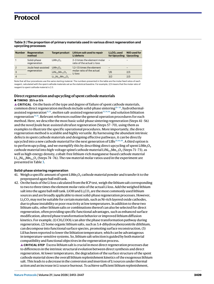
The spent materials were then directly recycled using solid-phase regeneration and Joule heat-assisted regeneration methods, employing a muffle furnace and Joule heat device, respectively. For the solid-phase method, additional water washing and re-sintering steps were included to ensure complete recycling. Using the Joule heat method, we also demonstrated one-step direct upcycling of spent LiMn 2 O4. The two classic cathode materials, LiNi 0.5 Mn1.5 O4 and Li 1.2 Ni0.2 Mn0.6 O2, which show potential for future market applications, are used here as examples to demonstrate the versatility of this method. Researchers can adapt this process to produce manganese-based materials with other components, depending on specific experimental needs. This includes layered Li-rich materials with the classic composition of Li 1.2 Ni0.13 Co0.13 Mn0.54 O2, rock salt-phase Mn-based Li-rich materials and others. Additionally, the method can be combined with conventional modification techniques, such as element doping and surface engineering, to further optimize material performance.
SECTION | page 8 | Docling页内原序 1 | 新页内顺序 1 | layout_order 252 | top_margin / left | p8:body_region:0
Protocol
SECTION | page 8 | Docling页内原序 2 | 新页内顺序 2 | layout_order 253 | front_matter / left | p8:body_region:0
Regenerated cathode material characterization
#043 | page 8 | Docling页内原序 3 | 新页内顺序 3 | layout_order 254 | front_matter / left_crossing | p8:body_region:0
The regenerated cathode materials were characterized using multiple techniques: ICP-OES to confirm elemental replenishment, XRD to assess phase evolution, scanning electron microscopy (SEM) to analyze microscopic morphology, transmission electron microscopy (TEM) to study local lattice phase structures and electron paramagnetic resonance (EPR) to evaluate the impact of the nonequilibrium phase repair process on material defect behavior.
SECTION | page 8 | Docling页内原序 4 | 新页内顺序 4 | layout_order 255 | front_matter / left | p8:body_region:0
Electrochemical performance verification
#044 | page 8 | Docling页内原序 5 | 新页内顺序 5 | layout_order 256 | front_matter / left_crossing | p8:body_region:0
Finally, to evaluate the regeneration and upcycling performance, the recycled material powder was mixed with NMP and polyvinylidene difluoride (PVDF), coated onto Al foil to fabricate electrodes and assembled into half-cells with Li metal as the counter electrode. Long-cycle and rate performance tests were conducted, and the results were compared with those of the spent materials and commercial materials.
SECTION | page 8 | Docling页内原序 6 | 新页内顺序 6 | layout_order 257 | front_matter / left | p8:body_region:0
Key steps of the protocol
#045 | page 8 | Docling页内原序 7 | 新页内顺序 7 | layout_order 258 | front_matter / left_crossing | p8:body_region:0
Based on experimental experience, the key steps affecting the direct regeneration process for interdisciplinary researchers new to this field are as follows:
#046 | page 8 | Docling页内原序 8 | 新页内顺序 8 | layout_order 259 | front_matter / left | p8:body_region:0
Thoroughly discharge the spent batteries (Step 3).
#047 | page 8 | Docling页内原序 9 | 新页内顺序 9 | layout_order 260 | front_matter / left_crossing | p8:body_region:0
Effectively clean the collected cathode material powder to completely remove impurities (Steps 11-17).
#048 | page 8 | Docling页内原序 10 | 新页内顺序 10 | layout_order 261 | front_matter / left_crossing | p8:body_region:0
Accurately determine the lithium replenishment amount on the basis of failure analysis and the lithium replenishment mechanism (Steps 40, 42).
#049 | page 8 | Docling页内原序 11 | 新页内顺序 11 | layout_order 262 | front_matter / left_crossing | p8:body_region:0
Optimize the heat treatment process by setting the environment, temperature, duration, and procedure according to the material's condition (Steps 51, 67, 73, 76).
#050 | page 8 | Docling页内原序 12 | 新页内顺序 12 | layout_order 263 | front_matter / left | p8:body_region:0
Water washing and re-sintering steps (Steps 52-56).
SECTION | page 8 | Docling页内原序 13 | 新页内顺序 13 | layout_order 264 | front_matter / left | p8:body_region:0
Special reminder
#051 | page 8 | Docling页内原序 14 | 新页内顺序 14 | layout_order 265 | front_matter / left_crossing | p8:body_region:0
Before adopting the processes described in research papers claiming to achieve direct recycling of spent cathode materials, carefully examine the charge and discharge curves of the spent cathode materials presented in the literature. In some cases, if the charge-specific capacity is extremely low but the discharge-specific capacity is high or even close to the standard specific capacity, the material being treated may not be an actual spent cathode material. Instead, it could be a lithium-deficient cathode material created through electrochemical or chemical delithiation. As a result, the regeneration methods described in these studies may not be fully applicable to the treatment of actual spent cathode materials.
SECTION | page 8 | Docling页内原序 15 | 新页内顺序 15 | layout_order 266 | body_zone / left | p8:body_region:0
Materials
SECTION | page 8 | Docling页内原序 16 | 新页内顺序 16 | layout_order 267 | body_zone / left | p8:body_region:0
Reagents
#052 | page 8 | Docling页内原序 17 | 新页内顺序 17 | layout_order 268 | body_zone / left_crossing | p8:body_region:0
▲ CAUTION Some reagents used in this protocol are volatile solvents or strong acids that can corrode the skin or damage the respiratory system. The experiment must be conducted in a qualified chemical laboratory equipped with essential safety facilities, including eyewashes and fire-fighting equipment. Operators must wear appropriate personal protective equipment, such as laboratory coats, explosion-proof goggles and nitrile gloves. The preparation of precursor solutions should be carried out in a ventilated fume hood and clearly marked with caution labels. All chemicals must be stored in appropriate cabinets or explosion-proof refrigerators. Before use, refer to the Material Safety Data Sheet ( for proper handling and storage instructions.
#053 | page 8 | Docling页内原序 18 | 新页内顺序 18 | layout_order 269 | body_zone / left | p8:body_region:0
Spent lithium manganate pouch cell (LiMn 2 O4, Ronbay)
#054 | page 8 | Docling页内原序 19 | 新页内顺序 19 | layout_order 270 | bottom_margin / left_crossing | p8:body_region:0
▲ CAUTION Spent lithium-ion pouch cells pose a fire hazard. When heated, ruptured or exhibiting abnormal phenomena such as bloating, they can burn or explode. Store them in explosion-proof boxes whenever possible.
SECTION | page 9 | Docling页内原序 1 | 新页内顺序 1 | layout_order 273 | top_margin / left |
Protocol
#055 | page 9 | Docling页内原序 2 | 新页内顺序 2 | layout_order 274 | page_body / left |
Sodium chloride (NaCl, 99.5%, Macklin, cat. no. S805275)
#056 | page 9 | Docling页内原序 3 | 新页内顺序 3 | layout_order 275 | page_body / left |
DMC (98%, Macklin, cat. no. D807386)
#057 | page 9 | Docling页内原序 4 | 新页内顺序 4 | layout_order 276 | page_body / left_crossing |
▲ CAUTION DMC is a slightly toxic organic solvent. Always wear appropriate protective equipment when handling it, avoid contact with skin and eyes and prevent inhalation of vapors and fumes. Keep it away from heat sources and use it in a well-ventilated fume hood.
#058 | page 9 | Docling页内原序 5 | 新页内顺序 5 | layout_order 277 | page_body / left |
NMP (>99.5%, Macklin, cat. no. M813015)
#059 | page 9 | Docling页内原序 6 | 新页内顺序 6 | layout_order 278 | page_body / left_crossing |
▲ CAUTION NMP is a slightly toxic organic solvent. Always wear appropriate protective equipment when handling it, avoid contact with skin and eyes and prevent inhalation of vapors and fumes. Keep it away from heat sources and use it in a well-ventilated fume hood.
#060 | page 9 | Docling页内原序 7 | 新页内顺序 7 | layout_order 279 | page_body / left |
Phytic acid (50%, Macklin, cat. no. P816021)
#061 | page 9 | Docling页内原序 8 | 新页内顺序 8 | layout_order 280 | page_body / left_crossing |
▲ CAUTION Phytic acid is strongly acidic. Always wear appropriate protective equipment when handling it, avoid contact with skin and eyes. Store it in a cool and dry place.
#062 | page 9 | Docling页内原序 9 | 新页内顺序 9 | layout_order 281 | page_body / left |
Anhydrous ethanol (99.7%, Macklin, cat. no. E809061)
#063 | page 9 | Docling页内原序 10 | 新页内顺序 10 | layout_order 282 | page_body / left_crossing |
▲ CAUTION Anhydrous ethanol is highly volatile and extremely flammable. Keep it away from heat sources during both use and storage.
#064 | page 9 | Docling页内原序 11 | 新页内顺序 11 | layout_order 283 | page_body / left_crossing |
Sodium hydroxide (NaOH, 95%, Macklin, cat. no. S835850)
#065 | page 9 | Docling页内原序 12 | 新页内顺序 12 | layout_order 284 | page_body / left_crossing |
▲ CAUTION NaOH is a strong alkali with serious irritant and corrosive properties. Its dust or fumes can irritate the eyes and respiratory tract, while direct contact with skin or eyes can cause burns. Always wear protective gloves and goggles during handling and avoid direct contact.
#066 | page 9 | Docling页内原序 13 | 新页内顺序 13 | layout_order 285 | page_body / left_crossing |
Concentrated hydrochloric acid (HCl, 37%, Aladdin, cat. no. H399657)
#067 | page 9 | Docling页内原序 14 | 新页内顺序 14 | layout_order 286 | page_body / left_crossing |
▲ CAUTION Concentrated HCl is a highly corrosive and volatile strong acid with strong irritant properties. Its fumes can severely irritate the eyes and respiratory tract, while direct contact with skin or eyes can cause irreversible damage. Always wear protective gloves and goggles when handling materials. Avoid direct contact with substances and ensure that the process is conducted in a well-ventilated fume hood.
#068 | page 9 | Docling页内原序 16 | 新页内顺序 16 | layout_order 288 | page_body / left_crossing |
▲ CAUTION Concentrated HNO3 is a highly corrosive and volatile strong acid with strong irritant properties. Its fumes can severely irritate the eyes and respiratory tract, while direct contact with skin or eyes can cause irreversible damage. Always wear protective gloves and goggles when handling materials. Avoid direct contact with substances and ensure that the process is conducted in a well-ventilated fume hood.
#069 | page 9 | Docling页内原序 18 | 新页内顺序 18 | layout_order 290 | page_body / left_crossing |
▲ CAUTION Store in ventilated dry place, pay attention to prevent rain and water.
#070 | page 9 | Docling页内原序 19 | 新页内顺序 19 | layout_order 291 | page_body / left_crossing |
Lithium hydroxide (LiOH, 98%, Macklin, cat. no. L812391)
#071 | page 9 | Docling页内原序 21 | 新页内顺序 21 | layout_order 293 | page_body / left_crossing |
Lithium acetate (CH 3 COOLi, 99.99%, Aladdin, cat. no. L118858)
#072 | page 9 | Docling页内原序 23 | 新页内顺序 23 | layout_order 295 | page_body / left |
Nickel oxide (NiO, 99%, Aladdin, cat. no. N108314)
#073 | page 9 | Docling页内原序 24 | 新页内顺序 24 | layout_order 296 | page_body / left_crossing |
▲ CAUTION May cause sensitization by skin contact. May cause cancer by inhalation. Wear suitable protective clothing and gloves when handling it. Store it in a dry and clean warehouse. Keep it away from fire and heat sources.
#074 | page 9 | Docling页内原序 27 | 新页内顺序 27 | layout_order 299 | page_body / left_crossing |
▲ CAUTION PVDF is prone to decomposition when exposed to water. Keep it away from moisture and store it in a dryer or glove box.
#075 | page 9 | Docling页内原序 28 | 新页内顺序 28 | layout_order 300 | page_body / left_crossing |
Acetylene black (99.9%, Canrd, cat. no. MA-EN-CO-040161)
#076 | page 9 | Docling页内原序 29 | 新页内顺序 29 | layout_order 301 | page_body / left |
Aluminum foil (99.999%, Cailiaoren, cat. no. KY05748)
#077 | page 9 | Docling页内原序 30 | 新页内顺序 30 | layout_order 302 | page_body / left_crossing |
Lithium ion battery electrolyte (1 M LiPF 6 solution in EC:DMC:DEC of 1:1:1 vol%, DoDoChem, cat. no. 21324-40-3)
#078 | page 9 | Docling页内原序 31 | 新页内顺序 31 | layout_order 303 | bottom_margin / left_crossing |
▲ CAUTION Electrolyte is a slightly toxic solvent. Always wear appropriate protective equipment when handling it, avoid contact with skin and eyes. Store it in glove box.
SECTION | page 10 | Docling页内原序 1 | 新页内顺序 1 | layout_order 307 | top_margin / left |
Protocol
#079 | page 10 | Docling页内原序 2 | 新页内顺序 2 | layout_order 308 | page_body / left |
Li metal chip (Li, China Aviation Lithium Battery)
#080 | page 10 | Docling页内原序 3 | 新页内顺序 3 | layout_order 309 | page_body / left_crossing |
▲ CAUTION Li metal is highly reactive and corrosive, capable of causing irritation or burns to the eyes and skin. It oxidizes and deteriorates quickly when exposed to air, releasing hydrogen and potentially producing sparks when reacting with water. Store and handle it in an inert environment, such as a glove box, to ensure safety.
#081 | page 10 | Docling页内原序 4 | 新页内顺序 4 | layout_order 310 | page_body / left_crossing |
Commercial LiMn2O4 cathode powder (Canrd, cat. no. MA-EN-CA-001601)
#082 | page 10 | Docling页内原序 5 | 新页内顺序 5 | layout_order 311 | page_body / left_crossing |
▲ CAUTION Keep it away from moisture and store it in a dryer or glove box.
#083 | page 10 | Docling页内原序 6 | 新页内顺序 6 | layout_order 312 | page_body / left_crossing |
Commercial Li1.2 Ni0.2 Mn0.6 O2 cathode powder (Canrd, cat. no. MA-EN-CA-0043)
#084 | page 10 | Docling页内原序 7 | 新页内顺序 7 | layout_order 313 | page_body / left_crossing |
▲ CAUTION Keep it away from moisture and store it in a dryer or glove box.
#085 | page 10 | Docling页内原序 8 | 新页内顺序 8 | layout_order 314 | page_body / left_crossing |
Commercial LiNi0.5 Mn1.5 O4 cathode powder (Canrd, cat. no. MA-EN-CA-000103)
#086 | page 10 | Docling页内原序 9 | 新页内顺序 9 | layout_order 315 | page_body / left_crossing |
▲ CAUTION Keep it away from moisture and store it in a dryer or glove box.
SECTION | page 10 | Docling页内原序 10 | 新页内顺序 10 | layout_order 316 | page_body / left |
Equipment
#087 | page 10 | Docling页内原序 11 | 新页内顺序 11 | layout_order 317 | page_body / left_crossing |
Deionized pure water machine (Ulupure, model no. UPH-11-10TNP)
#088 | page 10 | Docling页内原序 13 | 新页内顺序 13 | layout_order 319 | page_body / left |
Digital multimeter (Victor, model no. VC890C)
#089 | page 10 | Docling页内原序 15 | 新页内顺序 15 | layout_order 321 | page_body / left_crossing |
▲ CAUTION Heating equipment, ensure the furnace temperature has stabilized at a safe level before opening the door during use and ensure the environment is ventilated to avoid affect the sintering process. Always wear heat-insulating gloves when handling samples to prevent burns.
#090 | page 10 | Docling页内原序 16 | 新页内顺序 16 | layout_order 322 | page_body / left_crossing |
Constant temperature blast oven (Shanghai Jinghong, model no. DHG-9031A)
#091 | page 10 | Docling页内原序 17 | 新页内顺序 17 | layout_order 323 | page_body / left_crossing |
▲ CAUTION Heating equipment, ensure the furnace temperature has stabilized at a safe level before opening the door during use. Always wear heat-insulating gloves when handling samples to prevent burns.
#092 | page 10 | Docling页内原序 19 | 新页内顺序 19 | layout_order 325 | page_body / left_crossing |
▲ CAUTION Heating equipment, ensure the furnace temperature has stabilized at a safe level before opening the door during use. Always wear heat-insulating gloves when handling samples to prevent burns.
#093 | page 10 | Docling页内原序 20 | 新页内顺序 20 | layout_order 326 | page_body / left |
Filtration device (Delvstlab, model no. 250ml)
#094 | page 10 | Docling页内原序 24 | 新页内顺序 24 | layout_order 330 | page_body / left_crossing |
▲ CAUTION Inert gas protection equipment. Water content less than 0.01 ppm, oxygen content less than 0.01 ppm. During the operation, care should be taken to protect the working gloves from being damaged.
#095 | page 10 | Docling页内原序 27 | 新页内顺序 27 | layout_order 333 | page_body / left |
X-ray diffractometer (Rigaku, model no. MiniFlex600)
#096 | page 10 | Docling页内原序 28 | 新页内顺序 28 | layout_order 334 | page_body / left_crossing |
▲ CAUTION X-ray radiation equipment, do not open the protective cover door during the experiment. Take precautions to avoid direct exposure to X-rays and, if possible, wear protective equipment to minimize radiation exposure.
#097 | page 10 | Docling页内原序 30 | 新页内顺序 30 | layout_order 336 | page_body / left_crossing |
▲ CAUTION Heating equipment, ensure the cavity temperature has stabilized at a safe level before opening the door during use. Always wear heat-insulating gloves when handling samples to prevent burns.
#098 | page 10 | Docling页内原序 31 | 新页内顺序 31 | layout_order 337 | page_body / left |
Planetary ball mill (Mitr, model no. YXQM-1L)
#099 | page 10 | Docling页内原序 32 | 新页内顺序 32 | layout_order 338 | page_body / left_crossing |
▲ CAUTION Rotary grinding equipment. Ensure that the device has come to a complete stop and has reached a safe level before opening the door during use.
#100 | page 10 | Docling页内原序 34 | 新页内顺序 35 | layout_order 341 | bottom_margin / left_crossing |
▲ CAUTION Heating equipment, ensure the furnace temperature has stabilized at a safe wear heat-insulating gloves when handling samples to prevent burns.
#101 | page 10 | Docling页内原序 36 | 新页内顺序 36 | layout_order 342 | bottom_margin / left_crossing |
Field-emission scanning electron microscope (ZEISS, model no. SUPRA-55)
SECTION | page 11 | Docling页内原序 1 | 新页内顺序 1 | layout_order 345 | top_margin / left | p11:body_region:0
Protocol
#102 | page 11 | Docling页内原序 2 | 新页内顺序 2 | layout_order 346 | page_body / left_crossing | p11:body_region:0
Field-emission transmission electron microscope (JEOL, model no. JEOL-3200FS)
#103 | page 11 | Docling页内原序 3 | 新页内顺序 3 | layout_order 347 | page_body / left | p11:body_region:0
TEM sample holder (JEOL, model no. EM-31640)
#104 | page 11 | Docling页内原序 5 | 新页内顺序 5 | layout_order 349 | page_body / left_crossing | p11:body_region:0
X-ray photoelectron spectroscopy (XPS) (Thermo Fisher, model no. ESCA LAB 220I-XL)
#105 | page 11 | Docling页内原序 6 | 新页内顺序 6 | layout_order 350 | page_body / left_crossing | p11:body_region:0
Analytical balance (Sartorius, model no. BSA224S-CW, 0.1 mg resolution)
#106 | page 11 | Docling页内原序 7 | 新页内顺序 7 | layout_order 351 | page_body / left_crossing | p11:body_region:0
Analytical balance (Sartorius, model no. QUINTIX65-1CN, 0.01 mg resolution)
#107 | page 11 | Docling页内原序 8 | 新页内顺序 8 | layout_order 352 | page_body / left_crossing | p11:body_region:0
Slurry defoaming machine (Sienox, model no. SIE-MIX90)
#108 | page 11 | Docling页内原序 10 | 新页内顺序 10 | layout_order 354 | page_body / left_crossing | p11:body_region:0
▲ CAUTION Operate it inside a fume hood to facilitate the extraction and adsorption of a large amount of volatile organic solvents. Always wear appropriate protective equipment when handling it, avoid contact with skin and eyes, and prevent inhalation of vapors and fumes.
#109 | page 11 | Docling页内原序 12 | 新页内顺序 12 | layout_order 356 | page_body / left_crossing | p11:body_region:0
Battery sealing machine (Shenzhen Kejing Star Tech., model no. MSK-110)
#110 | page 11 | Docling页内原序 13 | 新页内顺序 13 | layout_order 357 | page_body / left | p11:body_region:0
Battery test system (NEWARE, model no. CT-4008T-5V)
#111 | page 11 | Docling页内原序 14 | 新页内顺序 14 | layout_order 358 | page_body / left | p11:body_region:0
500 mesh sieve (Lvruo, model no. 52152)
#112 | page 11 | Docling页内原序 15 | 新页内顺序 15 | layout_order 359 | page_body / left | p11:body_region:0
Pipette (DLAB Scientific, model no. YEA2BAH0062949)
#113 | page 11 | Docling页内原序 16 | 新页内顺序 16 | layout_order 360 | page_body / left_crossing | p11:body_region:0
200 mesh copper mesh (Canrd, model no. MA-EN-CU-0018)
SECTION | page 11 | Docling页内原序 18 | 新页内顺序 18 | layout_order 362 | page_body / left | p11:body_region:0
Software
SECTION | page 11 | Docling页内原序 20 | 新页内顺序 20 | layout_order 364 | page_body / left | p11:body_region:0
Reagent setup
SECTION | page 11 | Docling页内原序 21 | 新页内顺序 21 | layout_order 365 | page_body / left | p11:body_region:0
Deionized water
#114 | page 11 | Docling页内原序 22 | 新页内顺序 22 | layout_order 366 | page_body / left_crossing | p11:body_region:0
In this protocol, the deionized water was self-produced by the laboratory Ulupure de-ion pure water system (tap water source), with a resistivity of 13-17.5 MΩ/cm at 25 °C and heavy metal ion <0.1 ppb.
SECTION | page 11 | Docling页内原序 23 | 新页内顺序 23 | layout_order 367 | page_body / left | p11:body_region:0
Others
#115 | page 11 | Docling页内原序 24 | 新页内顺序 24 | layout_order 368 | page_body / left_crossing | p11:body_region:0
The setup process for other reagents involved in this protocol is detailed in the 'Procedure' section.
SECTION | page 11 | Docling页内原序 25 | 新页内顺序 25 | layout_order 369 | page_body / left | p11:body_region:0
Equipment setup
SECTION | page 11 | Docling页内原序 26 | 新页内顺序 26 | layout_order 370 | page_body / left | p11:body_region:0
Glass/plastic equipment
#116 | page 11 | Docling页内原序 27 | 新页内顺序 27 | layout_order 371 | page_body / left_crossing | p11:body_region:0
All glass or plastic utensils used in this protocol must be thoroughly cleaned with detergent before use. Rinse them sequentially with tap water, deionized water and anhydrous ethanol. Then, dry the utensils in blast oven at 60 °C and use a ear bulb to remove any remaining sticky impurities.
SECTION | page 11 | Docling页内原序 28 | 新页内顺序 28 | layout_order 372 | page_body / left | p11:body_region:0
Others
#117 | page 11 | Docling页内原序 29 | 新页内顺序 29 | layout_order 373 | page_body / left_crossing | p11:body_region:0
The setup process for other reagents involved in this protocol is detailed in the 'Procedure' section.
SECTION | page 11 | Docling页内原序 30 | 新页内顺序 30 | layout_order 374 | page_body / left | p11:body_region:0
Software setup
SECTION | page 11 | Docling页内原序 31 | 新页内顺序 31 | layout_order 375 | page_body / left | p11:body_region:0
Techno-economic analysis setup
#118 | page 11 | Docling页内原序 32 | 新页内顺序 32 | layout_order 376 | bottom_margin / left_crossing | p11:body_region:0
In this protocol, we conduct a techno-economic analysis of various recycling technology routes using a standardized benchmark of one ton of spent LiMn 2 O4//graphite pouch batteries. Costs are categorized into raw materials, reagents, labor, energy and water, equipment depreciation, pretreatment and environmental protection. As production process costs-including
SECTION | page 12 | Docling页内原序 1 | 新页内顺序 1 | layout_order 379 | top_margin / left | p12:body_region:0
Protocol
#119 | page 12 | Docling页内原序 2 | 新页内顺序 2 | layout_order 380 | page_body / left_crossing | p12:body_region:0
equipment depreciation, labor and other factors-are difficult to estimate directly, we use data from the EverBatt 2023 database (provided by Argonne National Laboratory) to derive specific values. To calculate potential benefits, we assume that all recovered components have some value that offsets recycling costs. However, since the actual value of separators, electrolytes and shells is difficult to determine, these items are excluded from our benefit analysis. Detailed process-based cost and revenue models are provided in the original data for the technoeconomic analysis (Supplementary Table 1). The total life-cycle energy consumption and greenhouse gas emissions for the three recycling processes encompass material use, energy and process emissions, and are also evaluated using the EverBatt model.
SECTION | page 12 | Docling页内原序 3 | 新页内顺序 3 | layout_order 381 | page_body / left | p12:body_region:0
FullProf refinement setup
#120 | page 12 | Docling页内原序 4 | 新页内顺序 4 | layout_order 382 | page_body / left_crossing | p12:body_region:0
In this protocol, XRD patterns of the powdered sample were refined using the FullProf program. The specific refinement sequence is as follows:
#121 | page 12 | Docling页内原序 14 | 新页内顺序 14 | layout_order 392 | page_body / left | p12:body_region:0
Atomic displacement parameters for each atom
#122 | page 12 | Docling页内原序 15 | 新页内顺序 15 | layout_order 393 | page_body / left_crossing | p12:body_region:0
During the refinement steps 1-9, new parameters are added sequentially in the specified
#123 | page 12 | Docling页内原序 16 | 新页内顺序 16 | layout_order 394 | page_body / left_crossing | p12:body_region:0
order for synchronous refinement. Once the atomic occupancy refinement converges, that parameter is deselected and each atom's displacement parameters are refined independently. If a parameter substantially deviates from its expected value, it is necessary to adjust the refinement sequence and flexibly modify the preset values. Throughout the refinement process, all parameters are constrained within ranges of physical relevance, and the final confidence factor is ensured to remain within a reasonable range.
SECTION | page 12 | Docling页内原序 17 | 新页内顺序 17 | layout_order 395 | page_body / left | p12:body_region:0
Procedure
SECTION | page 12 | Docling页内原序 18 | 新页内顺序 18 | layout_order 396 | page_body / left | p12:body_region:0
Spent battery disassembly and pretreatment
SECTION | page 12 | Docling页内原序 19 | 新页内顺序 19 | layout_order 397 | page_body / left | p12:body_region:0
● TIMING 45 h
#124 | page 12 | Docling页内原序 20 | 新页内顺序 20 | layout_order 398 | page_body / left_crossing | p12:body_region:0
▲ CRITICAL There are two main methods for obtaining spent LIB electrode materials 29,51 . One involves manually disassembling the batteries to obtain spent cathode/anode material powder (Steps 1-8). The other involves sourcing black mass directly from battery disassembly manufacturers, who produce it by crushing and sorting waste batteries. In this protocol, the treatment of such black mass begins at the pretreatment stage (Step 9).
#125 | page 12 | Docling页内原序 21 | 新页内顺序 21 | layout_order 399 | page_body / left_crossing | p12:body_region:0
Evaluate the basic information and condition of spent LIBs, including battery type, state of health and state of charge. This evaluation relies mainly on information from sources such as the battery nameplate, battery passport and basic electrochemical testing. For batteries lacking essential information, simple pulse testing combined with machine learning based on feature engineering can provide an accurate evaluation 52,53 .
#126 | page 12 | Docling页内原序 22 | 新页内顺序 22 | layout_order 400 | page_body / left_crossing | p12:body_region:0
Prepare an aqueous NaCl solution and adjust the brine concentration to 10-15% (wt/vol%) by controlling the amount of NaCl added.
#127 | page 12 | Docling页内原序 23 | 新页内顺序 23 | layout_order 401 | page_body / left_crossing | p12:body_region:0
Transfer the spent LIBs into the prepared NaCl solution for chemical discharge, the solution should be added in a volume sufficient to fully submerge the spent LIBs. Adjust the soaking time on the basis of the battery type, and remove the batteries when their voltage drops below 1.5 V (Supplementary Fig. 4).
#128 | page 12 | Docling页内原序 24 | 新页内顺序 24 | layout_order 402 | bottom_margin / left_crossing | p12:body_region:0
▲ CAUTION The saltwater discharge process utilizes the battery's positive and negative electrodes as the cathode and anode, respectively, to consume the residual power through
SECTION | page 13 | Docling页内原序 1 | 新页内顺序 1 | layout_order 405 | top_margin / left | p13:body_region:0
Protocol
#129 | page 13 | Docling页内原序 2 | 新页内顺序 2 | layout_order 406 | page_body / left_crossing | p13:body_region:0
electrolysis in the solution. This process may generate harmful exhaust gases, so it is essential to implement protective measures and conduct the operation in professional equipment, such as fume hoods. Additionally, the wastewater generated after the reaction may contain leaked electrolytes, fluorides, acidic byproducts and potentially harmful heavy metal ions such as nickel, cobalt, manganese, copper and aluminum, as well as various organic pollutants. Owing to its toxicity and environmental risks, direct discharge of such wastewater is prohibited under environmental regulations. Therefore, it must be collected in designated chemical waste containers and handed over to certified hazardous waste disposal companies. The treatment process typically involves acid-base neutralization, heavy metal precipitation, organic pollutant removal, desalination, and further purification to meet discharge standards.
#130 | page 13 | Docling页内原序 3 | 新页内顺序 3 | layout_order 407 | page_body / left_crossing | p13:body_region:0
▲ CRITICAL STEP The discharge process must be fully completed. If necessary, a combination of physical and chemical discharge should be employed to ensure complete discharge of the spent battery. Physical discharge refers to the process of discharging a battery by connecting it to an external resistive load, allowing the remaining energy to be safely dissipated in the form of heat. Incomplete battery discharge impacts both safety and regeneration accuracy. From a safety perspective, partially discharged batteries retain more lithium on the anode electrode, increasing the risk of internal chemical reactions or short circuits during disassembly, which may lead to explosions or fires. From a recycling process standpoint, the cathode electrode in such batteries remains lithium deficient, potentially leading to misjudgment of material degradation and increased consumption of reagents during subsequent direct regeneration.
#131 | page 13 | Docling页内原序 4 | 新页内顺序 4 | layout_order 408 | page_body / left_crossing | p13:body_region:0
After discharge, transfer the spent LIBs to a vibration dehydrator to remove surface moisture, reducing it to less than 5%.
#132 | page 13 | Docling页内原序 5 | 新页内顺序 5 | layout_order 409 | page_body / left_crossing | p13:body_region:0
▲ CAUTION Before operating the vibration dehydrator, ensure that the safety door is properly closed. During use, carefully monitor the equipment's overall vibration amplitude. Excessive vibration can damage the equipment, lead to machine failure and even pose a risk to personal safety.
#133 | page 13 | Docling页内原序 6 | 新页内顺序 6 | layout_order 410 | page_body / left_crossing | p13:body_region:0
Select the appropriate tools to remove the aluminum plastic film or steel shell on the basis of the battery type. The main commercial types of LIBs include pouch cells, cylindrical cells and prismatic cells. Pouch cells typically have soft shells made of aluminum-plastic composite film, which can be easily removed with scissors. In contrast, cylindrical and prismatic cells have rigid shells made of nickel-plated steel and aluminum alloy, respectively, and usually require cutting tools for disassembly.
#134 | page 13 | Docling页内原序 7 | 新页内顺序 7 | layout_order 411 | page_body / left_crossing | p13:body_region:0
▲ CAUTION Take safety precautions to prevent cuts from sharp blades.
#135 | page 13 | Docling页内原序 8 | 新页内顺序 8 | layout_order 412 | page_body / left_crossing | p13:body_region:0
Separate the components inside the battery cell, including the Al foil current collector coated with cathode material, the Cu foil current collector coated with anode material and the diaphragm (Supplementary Fig. 5).
#136 | page 13 | Docling页内原序 9 | 新页内顺序 9 | layout_order 413 | page_body / left_crossing | p13:body_region:0
▲ CAUTION This step requires personal safety protection and should be carried out in a glove box whenever possible. If operating in a glove box is not feasible, ensure that gloves and masks are worn and the environment is well ventilated, as the electrolyte is highly volatile and potentially harmful. Additionally, take fire prevention precautions. After disassembly, close attention should be paid to the color of the negative electrode. If the graphite anode appears dark yellow or golden yellow, it indicates a high residual lithium content, which is highly reactive and may ignite upon contact with water or other reagents.
#137 | page 13 | Docling页内原序 10 | 新页内顺序 10 | layout_order 414 | page_body / left_crossing | p13:body_region:0
Soak the electrode coated with active material in DMC solvent to remove residual electrolyte and side reaction products. Take it out after standing for 20 min, wipe it and dry it.
#138 | page 13 | Docling页内原序 11 | 新页内顺序 11 | layout_order 415 | page_body / left_crossing | p13:body_region:0
■ PAUSE POINT Long-term storage in a normal atmospheric environment can lead to further embrittlement and phase changes of the electrodes and active materials, making recycling more challenging. It is recommended to transfer them to a dry room or glove box as soon as possible.
#139 | page 13 | Docling页内原序 12 | 新页内顺序 12 | layout_order 416 | bottom_margin / left_crossing | p13:body_region:0
Strip the active material of spent LiMn 2 O4 cathode powder from the current collector. Three methods can be chosen on the basis of the electrode characteristics. In most cases, mechanical
SECTION | page 14 | Docling页内原序 1 | 新页内顺序 1 | layout_order 419 | top_margin / left |
Protocol
#140 | page 14 | Docling页内原序 2 | 新页内顺序 2 | layout_order 420 | page_body / left_crossing |
separation is broadly applicable, but the process is relatively labor intensive and unsuitable for large-scale applications. Heat treatment separation requires careful consideration of the cathode material's thermal stability to avoid degradation. Solution-based separation is more appropriate for electrodes using water-based binders. For electrodes with organic binders, a suitable solvent system must be selected on the basis of the literature.
#141 | page 14 | Docling页内原序 3 | 新页内顺序 3 | layout_order 421 | page_body / left_crossing |
Mechanical separation: use a knife, spoon, or other hard objects to separate the active material powder from the current collector
#142 | page 14 | Docling页内原序 4 | 新页内顺序 4 | layout_order 422 | page_body / left_crossing |
Heat treatment separation: transfer the electrode to a muffle furnace and heat it to 400 °C for 20 min to inactivate the binder and separate the active material from the current collector
#143 | page 14 | Docling页内原序 5 | 新页内顺序 5 | layout_order 423 | page_body / left_crossing |
Solution treatment separation: prepare a solution using phytic acid or other substances, and soak the electrode for 5 min to inactivate the binder and separate the active material 54 . If the binder is water based, separation can be achieved by water immersion combined with ultrasonic treatment
#144 | page 14 | Docling页内原序 7 | 新页内顺序 7 | layout_order 425 | page_body / left_crossing |
Transfer the collected spent LiMn 2 O4 cathode powder to an agate mortar and grind it to separate the agglomerated and flaked particles.
#145 | page 14 | Docling页内原序 8 | 新页内顺序 8 | layout_order 426 | page_body / left_crossing |
Sieve the ground powder through a 500 mesh sieve to remove large impurities and agglomerates.
#146 | page 14 | Docling页内原序 9 | 新页内顺序 9 | layout_order 427 | page_body / left_crossing |
Transfer the spent cathode powder to an NMP reagent for cleaning, with a solid:liquid ratio of ~1:20. Stir the mixture for 3 h at 500 rpm.
#147 | page 14 | Docling页内原序 10 | 新页内顺序 10 | layout_order 428 | page_body / left_crossing |
▲ CAUTION NMP is volatile and irritating. During operation, avoid contact with skin and eyes, inhalation and exposure to fire.
#148 | page 14 | Docling页内原序 11 | 新页内顺序 11 | layout_order 429 | page_body / left_crossing |
▲ CRITICAL STEP The cleaning process directly affects the performance of the subsequent direct regeneration of materials. Residual fluorine-containing organic impurities may diffuse into the bulk phase and react on the surface during the subsequent heating repair process, disrupting the original balance between the repair reaction and thermal decomposition. This step is especially critical when treating black mass raw materials.
#149 | page 14 | Docling页内原序 12 | 新页内顺序 12 | layout_order 430 | page_body / left_crossing |
Separate the material by suction filtration and then wash three times with ethanol. Each wash follows a standard procedure: ethanol is gently poured along a glass rod onto the sediment on the filter paper until it is fully submerged. After allowing it to stand for 1 min, a vacuum pump is activated to draw the liquid through the filter.
#150 | page 14 | Docling页内原序 13 | 新页内顺序 13 | layout_order 431 | page_body / left_crossing |
Transfer the treated cathode powder to a blast oven at 100 °C and leave it there until it is completely dry.
#151 | page 14 | Docling页内原序 14 | 新页内顺序 14 | layout_order 432 | page_body / left_crossing |
Prepare an aqueous NaOH solution and adjust the concentration to 1 mol/L by controlling the amount of NaOH added.
#152 | page 14 | Docling页内原序 15 | 新页内顺序 15 | layout_order 433 | page_body / left_crossing |
▲ CAUTION NaOH is highly irritating and corrosive; therefore, safety precautions should be followed during this step, including wearing masks, protective glasses, and rubber gloves.
#153 | page 14 | Docling页内原序 16 | 新页内顺序 16 | layout_order 434 | page_body / left_crossing |
Transfer the spent LiMn 2 O4 cathode powder to the prepared NaOH solution and stirred to remove impurities, such as residual current collector debris. During the stirring process, the solid:liquid ratio is ~1:25, and the mixture is stirred at 500 rpm for 6 h.
#154 | page 14 | Docling页内原序 17 | 新页内顺序 17 | layout_order 435 | page_body / left_crossing |
Separate the powder and treated liquid by suction filtration and then wash three times with deionized water to completely remove the residual alkali solution. Except for the change of washing reagents, the operation process is the same as described in Step 12.
#155 | page 14 | Docling页内原序 18 | 新页内顺序 18 | layout_order 436 | page_body / left_crossing |
Transfer the treated cathode powder to a blast oven at 100 °C and leave it there until it is completely dry.
#156 | page 14 | Docling页内原序 19 | 新页内顺序 19 | layout_order 437 | page_body / left_crossing |
Collect all pretreated spent LiMn 2 O4 cathode powder and transfer it to a drying room or glove box for storage.
#157 | page 14 | Docling页内原序 20 | 新页内顺序 20 | layout_order 438 | bottom_margin / left_crossing |
■ PAUSE POINT Cathode materials readily absorb moisture, leading to hydrolysis reactions that generate surface impurities such as residual lithium and promote powder agglomeration. These materials may also react with O 2 and CO2 . This issue is particularly pronounced in spent cathode powders that, due to elemental loss and structural degradation, are more susceptible to reactions with H 2 O and CO2, potentially resulting in phenomena such as proton intercalation. Such reactions hinder subsequent direct
SECTION | page 15 | Docling页内原序 1 | 新页内顺序 1 | layout_order 441 | top_margin / left | p15:body_region:0
Protocol
#158 | page 15 | Docling页内原序 2 | 新页内顺序 2 | layout_order 442 | page_body / left_crossing | p15:body_region:0
regeneration processes, necessitating strict control of storage conditions. These conditions should also be tailored to the specific type of cathode material. For example, lithium iron phosphate is relatively insensitive to moisture and oxygen and can be stored in a standard dry environment for short durations, although long-term storage still requires moisture protection. In contrast, Ni-rich ternary layered oxides are more vulnerable to oxidation and require more stringent storage measures. Shelf life depends on both storage conditions and material type; for most sensitive materials, exposure to ambient air should be limited to no more than 24 h. Direct regeneration is recommended within 1-2 weeks if stored under dry air, or within several months if preserved in an inert atmosphere.
SECTION | page 15 | Docling页内原序 3 | 新页内顺序 3 | layout_order 443 | page_body / left | p15:body_region:0
Failure analysis of spent cathode materials
SECTION | page 15 | Docling页内原序 4 | 新页内顺序 4 | layout_order 444 | page_body / left | p15:body_region:0
● TIMING 2 h
#159 | page 15 | Docling页内原序 5 | 新页内顺序 5 | layout_order 445 | page_body / left_crossing | p15:body_region:0
▲ CRITICAL To achieve effective direct regeneration or upcycling of spent cathode materials and minimize material waste, it is essential to understand the material's failure state,
#160 | page 15 | Docling页内原序 6 | 新页内顺序 6 | layout_order 446 | page_body / left_crossing | p15:body_region:0
particularly the extent of lithium loss and the degradation of its phase structure.
#161 | page 15 | Docling页内原序 7 | 新页内顺序 7 | layout_order 447 | page_body / left_crossing | p15:body_region:0
Weigh 0.3 g of spent LiMn 2 O4 cathode material powder using an analytical balance and transfer it to a polytetrafluoroethylene digestion tank.
#162 | page 15 | Docling页内原序 8 | 新页内顺序 8 | layout_order 448 | page_body / left_crossing | p15:body_region:0
Prepare aqua regia by mixing concentrated hydrochloric acid and concentrated nitric acid in a 3:1 (vol/vol) ratio to digest the sample. The specific operation in this process is to slowly pour one volume of concentrated nitric acid into three volumes of concentrated hydrochloric acid while continuously stirring with a glass rod.
#163 | page 15 | Docling页内原序 9 | 新页内顺序 9 | layout_order 449 | page_body / left_crossing | p15:body_region:0
▲ CAUTION Both reagents are highly corrosive, and the chlorine gas they emit is toxic, making vapor contact extremely dangerous. Always conduct the preparation process in a fume hood and wear strong acid-resistant rubber gloves, masks and protective glasses.
#164 | page 15 | Docling页内原序 10 | 新页内顺序 10 | layout_order 450 | page_body / left_crossing | p15:body_region:0
Slowly add 3 mL of concentrated aqua regia to the polytetrafluoroethylene digestion tank and securely cap it.
#165 | page 15 | Docling页内原序 11 | 新页内顺序 11 | layout_order 451 | page_body / left_crossing | p15:body_region:0
Place the polytetrafluoroethylene digestion tank into the sleeve position of the rotor frame, insert the frame into the microwave digester and connect the temperature sensor.
#166 | page 15 | Docling页内原序 12 | 新页内顺序 12 | layout_order 452 | page_body / left_crossing | p15:body_region:0
Set the digestion program and start the microwave digestion process. Configure the temperature to 120 °C, the heating time to 5 min and the digestion time to 15 min.
#167 | page 15 | Docling页内原序 13 | 新页内顺序 13 | layout_order 453 | page_body / left_crossing | p15:body_region:0
▲ CAUTION Microwave digestion instruments emit microwave radiation during operation, which can pose health risks if used improperly or for extended periods. They also generate high pressures and temperatures, and in the event of equipment failure or operator error, explosions, fires or other hazardous situations may occur.
#168 | page 15 | Docling页内原序 14 | 新页内顺序 14 | layout_order 454 | page_body / left_crossing | p15:body_region:0
After completing digestion, remove the rotor frame and place it on a rotatable base inside a fume hood. Use a cap screwdriver to unscrew the pressure relief module, then remove the polytetrafluoroethylene digestion tank from the sleeve.
#169 | page 15 | Docling页内原序 15 | 新页内顺序 15 | layout_order 455 | page_body / left_crossing | p15:body_region:0
▲ CAUTION Remove the rotor frame only after the microwave digester cavity has sufficiently cooled to prevent risks such as burns to the experimenters or overpressure in the digestion tank.
#170 | page 15 | Docling页内原序 16 | 新页内顺序 16 | layout_order 456 | page_body / left_crossing | p15:body_region:0
Unscrew the digestion tank cap and check if the solution is clear and transparent to confirm that digestion is complete. Once confirmed, rinse any sample residue on the cap with deionized water and return it to the tank.
#171 | page 15 | Docling页内原序 17 | 新页内顺序 17 | layout_order 457 | page_body / left_crossing | p15:body_region:0
Transfer the digestion solution into a 50 mL volumetric flask. Rinse the digestion tank multiple times with small amounts of deionized water and combine the rinses in the flask. Dilute the solution to the mark with deionized water and mix thoroughly. This solution serves as the major element analysis solution.
#172 | page 15 | Docling页内原序 19 | 新页内顺序 19 | layout_order 459 | page_body / left_crossing | p15:body_region:0
Tighten the peristaltic pump tube, turn on the circulating cooling water. Ignite the plasma once the detector temperature reaches -40 °C.
#173 | page 15 | Docling页内原序 20 | 新页内顺序 20 | layout_order 460 | page_body / left_crossing | p15:body_region:0
Preheat for 10 min, then set the experimental method and configure the parameters for the test elements, conditions and standards.
#174 | page 15 | Docling页内原序 21 | 新页内顺序 21 | layout_order 461 | bottom_margin / left_crossing | p15:body_region:0
Measure the spectral intensity of each element in a series of standard solutions with varying concentrations and plot a standard curve.
SECTION | page 16 | Docling页内原序 1 | 新页内顺序 1 | layout_order 464 | top_margin / left | p16:body_region:0
Protocol
#175 | page 16 | Docling页内原序 2 | 新页内顺序 2 | layout_order 465 | page_body / left_crossing | p16:body_region:0
Introduce the blank solution and the sample solution into the ICP-OES equipment for analysis. Measure the spectral intensity of each element in both solutions, and calculate the element concentration from the working curve.
#176 | page 16 | Docling页内原序 3 | 新页内顺序 3 | layout_order 466 | page_body / left_crossing | p16:body_region:0
▲ CRITICAL STEP Analyzing the deficiency of various elements, especially Li, in the cathode material powder after cycling is a critical step in direct recycling, because it influences the choice of recycling method and the amount of reagents required.
#177 | page 16 | Docling页内原序 4 | 新页内顺序 4 | layout_order 467 | page_body / left_crossing | p16:body_region:0
Calculate the content of each element and the ratio using the formula:
#178 | page 16 | Docling页内原序 5 | 新页内顺序 5 | layout_order 468 | page_body / left_crossing | p16:body_region:0
where w is the element content; ρ1 and ρ0 are the concentrations of the element in the test and blank solutions, respectively; V is the volume of the test solution; f is the dilution factor; and m is the mass of the sample.
#179 | page 16 | Docling页内原序 6 | 新页内顺序 6 | layout_order 469 | page_body / left_crossing | p16:body_region:0
▲ CRITICAL STEP ICP-OES typically analyzes the relative proportions of various elements. When assessing the loss of elements in failed cathode powder, it is generally assumed that Li loss is substantially greater than that of other transition metals. As a result, the total amount of transition metals or the content of a specific transition metal is often used as a benchmark to estimate the relative content of Li and other elements. However, it is important to note that the dissolution of transition metal ions is also an intrinsic failure behavior of cathode materials 55,56 , which may lead to an underestimate of Li loss. Nevertheless, the error resulting from this underestimation is usually within an acceptable range, as the subsequent lithium replenishment process typically uses a substantial excess of lithium.
SECTION | page 16 | Docling页内原序 7 | 新页内顺序 7 | layout_order 470 | page_body / left | p16:body_region:0
◆ TROUBLESHOOTING
#180 | page 16 | Docling页内原序 8 | 新页内顺序 8 | layout_order 471 | page_body / left_crossing | p16:body_region:0
Clean the amorphous glass sample stage, slide and medicine spoon with anhydrous ethanol to remove contaminants, then dry them by blowing with an ear bulb.
#181 | page 16 | Docling页内原序 9 | 新页内顺序 9 | layout_order 472 | page_body / left_crossing | p16:body_region:0
Turn on the XRD equipment and the circulating cooling water system. Activate the high-voltage generator, set the voltage, current and other parameters, and wait for the equipment to reach the specified power.
#182 | page 16 | Docling页内原序 10 | 新页内顺序 10 | layout_order 473 | page_body / left_crossing | p16:body_region:0
Use a laboratory spoon to transfer the powder sample into the depression of the amorphous glass sample stage. Spread the sample evenly with a glass slide and press it to create a smooth plane. Remove any excess powder from the sample stage.
#183 | page 16 | Docling页内原序 11 | 新页内顺序 11 | layout_order 474 | page_body / left_crossing | p16:body_region:0
▲ CRITICAL STEP During sample preparation, the powder sample should completely fill the depressions in the amorphous glass sample stage, ensuring the sample plane is level with the stage to maximize reflected X-rays and achieve a more accurate XRD diffraction pattern.
#184 | page 16 | Docling页内原序 12 | 新页内顺序 12 | layout_order 475 | page_body / left_crossing | p16:body_region:0
Install the glass sample stage in the designated position of the XRD diffractometer. Adjust the stage so that the sample is aligned with the center of the X-ray beam, then tighten the stage and close the test chamber door.
#185 | page 16 | Docling页内原序 13 | 新页内顺序 13 | layout_order 476 | page_body / left_crossing | p16:body_region:0
Set the test parameters: the 2θ angle range to 10°-80°, the step size to 0.01°, and the time per step to 0.2 s. Use Cu Kα1 radiation ( λ = 1.5406 Å) for XRD measurements. ▲ CAUTION X-rays are highly harmful and can pose serious health risks. Never open the protective cover door during the experiment. Take precautions to prevent direct exposure to X-rays and, if possible, wear protective equipment to minimize radiation exposure. To improve data quality and reduce background noise, XRD data that
#186 | page 16 | Docling页内原序 14 | 新页内顺序 14 | layout_order 477 | page_body / left_crossing | p16:body_region:0
▲ CRITICAL STEP require refinement are typically collected using a slow scan method, which involves reducing the step size and extending the collection time per step.
#187 | page 16 | Docling页内原序 15 | 新页内顺序 15 | layout_order 478 | page_body / left_crossing | p16:body_region:0
Once the measurement is complete, open the test chamber door and recover the samples.
#188 | page 16 | Docling页内原序 16 | 新页内顺序 16 | layout_order 479 | page_body / left_crossing | p16:body_region:0
Analyse the collected XRD data for phase identification and use the FullProf program for refinement to extract information such as unit cell parameters, atomic occupancy and defect levels. Use this information to evaluate the material's failure state.
SECTION | page 16 | Docling页内原序 17 | 新页内顺序 17 | layout_order 480 | page_body / left | p16:body_region:0
◆ TROUBLESHOOTING
#189 | page 16 | Docling页内原序 18 | 新页内顺序 18 | layout_order 481 | bottom_margin / left_crossing | p16:body_region:0
On the basis of the results of a basic failure analysis of the spent cathode material powder, assess the degree of material degradation. Use this information to select an appropriate direct regeneration method and determine the amount of lithium salt required.
SECTION | page 17 | Docling页内原序 1 | 新页内顺序 1 | layout_order 484 | top_margin / left | p17:body_region:0
Protocol
#190 | page 17 | Docling页内原序 3 | 新页内顺序 3 | layout_order 486 | page_body / left_crossing | p17:body_region:0
Note that all four procedures use the same starting material. The numbers presented in the table are the molar feed ratios of each reagent, calculated with the spent cathode materials set as the statistical baseline. For example, 2/3 means that the molar ratio of reagent to spent cathode material is 2:3.
SECTION | page 17 | Docling页内原序 4 | 新页内顺序 4 | layout_order 487 | page_body / left_crossing | p17:body_region:0
Direct regeneration and upcycling of spent cathode materials
SECTION | page 17 | Docling页内原序 5 | 新页内顺序 5 | layout_order 488 | page_body / left | p17:body_region:0
● TIMING 35 h or 5 h
#191 | page 17 | Docling页内原序 6 | 新页内顺序 6 | layout_order 489 | page_body / left_crossing | p17:body_region:0
▲ CRITICAL On the basis of the type and degree of failure of spent cathode materials, common direct regeneration methods include solid-phase sintering 28-30 , hydrothermalassisted regeneration 31,32 , molten salt-assisted regeneration 33,34,46 and solution lithiation regeneration 35,36 . Relevant references outline the general operation procedures for each method. Here, we describe the most basic solid-phase sintering regeneration (Steps 41-56) and the novel Joule heat-assisted ultrafast regeneration (Steps 57-70), using them as examples to illustrate the specific operational procedures. More importantly, the direct regeneration method is scalable and highly versatile. By harnessing the abundant intrinsic defects in spent cathode materials and designing effective pathways, it can be directly upcycled into a new cathode material for the next generation of LIBs 28,46,48 . A third option is to perform upcycling, and we exemplify this by describing direct upcycling of spent LiMn 2 O4 cathode material into high-voltage spinel cathode material LiNi 0.5 Mn1.5 O4 (Steps 71-73), as well as high-energy density, cobalt-free lithium-rich manganese-based cathode material Li 1.2 Ni0.2 Mn0.6 O2 (Steps 74-76). The raw material molar ratios used in the experiment are presented in Table 3.
SECTION | page 17 | Docling页内原序 7 | 新页内顺序 7 | layout_order 490 | page_body / left | p17:body_region:0
Solid-phase sintering regeneration
#192 | page 17 | Docling页内原序 8 | 新页内顺序 8 | layout_order 491 | page_body / left_crossing | p17:body_region:0
Weigh a specific amount of spent LiMn 2 O4 cathode material powder and transfer it to the preprepared agate ball mill tank.
#193 | page 17 | Docling页内原序 9 | 新页内顺序 9 | layout_order 492 | page_body / left_crossing | p17:body_region:0
On the basis of the Li loss calculated from the ICP test, weigh the lithium salt corresponding to two to three times the element molar ratio of the actual Li loss. Add the weighed lithium salt into the agate ball mill tank. LiOH and Li 2 CO3 are the most commonly used lithium sources and are broadly applicable to most solid-phase regeneration processes. However, Li 2 CO3 may not be suitable for certain materials, such as Ni-rich layered oxide cathodes, due to phase instability or poor reactivity at low temperatures. In addition to these two lithium salts, other lithium salts or combinations thereof can also be selected for direct regeneration, often providing specific functional advantages, such as enhanced surface modification, altered phase transformation behavior or improved lithium diffusion kinetics. For example, (1) CH 3 COOLi can alter the phase transformation pathway during regeneration, (2) Some organic lithium salts, such as 3,4-dihydroxybenzonitrile dilithium, can decompose into functional surface species, promoting surface reconstruction, (3) LiI has been reported to lower the lithiation temperature, which can be advantageous in temperature-sensitive systems. So, lithium salt selection is guided by both material compatibility and functional objectives in the regeneration process.
#194 | page 17 | Docling页内原序 10 | 新页内顺序 10 | layout_order 493 | bottom_margin / left_crossing | p17:body_region:0
▲ CRITICAL STEP Excess lithium salt is crucial in most direct regeneration processes due to differences in the intrinsic structural evolution between direct synthesis and direct regeneration. At lower temperatures, the degradation of the surface structure of the spent cathode material slows the overall lithium replenishment kinetics of the exogenous lithium salt. This leads to a decrease in the conversion and insertion of Li sources under thermal action and an increase in Li source burnout. To achieve sufficient lithium replenishment,
SECTION | page 18 | Docling页内原序 1 | 新页内顺序 1 | layout_order 496 | top_margin / left | p18:body_region:0
Protocol
#195 | page 18 | Docling页内原序 2 | 新页内顺序 2 | layout_order 497 | page_body / left_crossing | p18:body_region:0
there are two main approaches: (1) enhance lithium replenishment kinetics by improving interfacial lithium salt adsorption, optimizing surface structure reconstruction and adjusting the reaction equilibrium state 37 and (2) compensate for the excessive Li source burnout by using an excess of lithium salts.
#196 | page 18 | Docling页内原序 3 | 新页内顺序 3 | layout_order 498 | page_body / left_crossing | p18:body_region:0
As the scale of single direct regeneration of spent cathode materials increases, such as from gram scale in the laboratory to kilogram scale in industry, the proportion of Li source burnout decreases, allowing for a reduction in overall usage of Li salt. In addition, according to experience, the required amount of excess lithium salt varies by cathode material type: layered oxides typically require the highest excess, spinel materials require a moderate amount and olivine materials require the least.
#197 | page 18 | Docling页内原序 4 | 新页内顺序 4 | layout_order 499 | page_body / left_crossing | p18:body_region:0
Gradually introduce anhydrous ethanol as a grinding aid, maintaining a powder to ethanol mass ratio of 1:2.
#198 | page 18 | Docling页内原序 5 | 新页内顺序 5 | layout_order 500 | page_body / left_crossing | p18:body_region:0
Add zirconia grinding beads to the agate ball mill tank as grinding media at a powder to grinding beads mass ratio of 1:3. Distribute the grinding beads as follows: 30% large, 50% medium and 20% small beads.
#199 | page 18 | Docling页内原序 6 | 新页内顺序 6 | layout_order 501 | page_body / left_crossing | p18:body_region:0
▲ CAUTION To ensure safety during the ball milling process, the total volume of grinding beads and material should not exceed 80% of the ball mill tank's capacity. A fill ratio of 40-60% is typically optimal.
#200 | page 18 | Docling页内原序 7 | 新页内顺序 7 | layout_order 502 | page_body / left_crossing | p18:body_region:0
Install an equal number of preweighed ball mill tanks into the diagonal positions of the planetary ball mill. Secure all the tanks by rotating the spiral buckle, then close the hatch. ▲ CAUTION Before starting ball milling, ensure that the ball mill tanks at the diagonal positions are balanced in weight and securely fixed. This prevents potential dangers, such as mechanical failure or material being thrown out due to center imbalance during the milling process.
#201 | page 18 | Docling页内原序 8 | 新页内顺序 8 | layout_order 503 | page_body / left_crossing | p18:body_region:0
Set up a brief program to run the ball mill at the experimental speed for a few minutes. Observe its operation closely, paying special attention to any unusual sounds, such as loose buckles, to ensure the ball mill is functioning normally.
#202 | page 18 | Docling页内原序 9 | 新页内顺序 9 | layout_order 504 | page_body / left_crossing | p18:body_region:0
Set the ball milling program according to the experimental conditions: adjust the speed to 400 rpm, set the total milling time to 4 h and alternate between forward and reverse rotation every 15 min.
#203 | page 18 | Docling页内原序 10 | 新页内顺序 10 | layout_order 505 | page_body / left_crossing | p18:body_region:0
▲ CAUTION During ball mill operation, the high-speed rotation and vibration can cause mechanical parts to wear, loosen or even break. As a result, objects may be ejected with substantial force, posing a safety risk. If you notice unusual sounds or vibrations, stop the equipment immediately.
#204 | page 18 | Docling页内原序 11 | 新页内顺序 11 | layout_order 506 | page_body / left_crossing | p18:body_region:0
After the ball milling process is completely stopped, loosen the buckle and remove the ball mill tanks. Observe the powder to ensure it is in a normal condition-fine, evenly dispersed and free of flakes or severe agglomeration. If so, transfer it to the blast oven for drying.
SECTION | page 18 | Docling页内原序 12 | 新页内顺序 12 | layout_order 507 | page_body / left | p18:body_region:0
◆ TROUBLESHOOTING
#205 | page 18 | Docling页内原序 13 | 新页内顺序 13 | layout_order 508 | page_body / left_crossing | p18:body_region:0
Scrape the dried powder out of the ball mill tanks. Transfer part of the material to an alumina porcelain boat and store the remaining material in a blast oven for later use.
#206 | page 18 | Docling页内原序 14 | 新页内顺序 14 | layout_order 509 | page_body / left_crossing | p18:body_region:0
Transfer the alumina porcelain boat to the muffle furnace, position it correctly and close the furnace chamber.
#207 | page 18 | Docling页内原序 15 | 新页内顺序 15 | layout_order 510 | page_body / left_crossing | p18:body_region:0
▲ CRITICAL STEP When the sintering volume of a single batch is large, avoid tightly packing the powder, as it can negatively impact the quality of the recycled material. To improve airflow, introduce a controlled gas flow path (Supplementary Fig. 6).
#208 | page 18 | Docling页内原序 16 | 新页内顺序 16 | layout_order 511 | page_body / left_crossing | p18:body_region:0
Set the solid-phase sintering program and activate the heating switch. Set the overall heating rate to 3 °C/min. Raise the temperature to 450 °C and maintain it for 2 h. Then, increase the temperature to 850 °C and hold it for 10 h. Finally, allow the sample to cool naturally to room temperature (30 °C).
#209 | page 18 | Docling页内原序 17 | 新页内顺序 17 | layout_order 512 | bottom_margin / left_crossing | p18:body_region:0
▲ CAUTION When a muffle furnace operates at high temperatures, flammable materials such as paper or plastic can ignite. Therefore, always inspect the experimental area for such materials before use. During operation, the furnace surface and door become extremely hot, creating a risk of burns if touched. After completing an experiment, allow the furnace to cool fully and wear heat-insulating gloves when removing samples to avoid injury.
SECTION | page 19 | Docling页内原序 1 | 新页内顺序 1 | layout_order 515 | top_margin / left |
Protocol
#210 | page 19 | Docling页内原序 2 | 新页内顺序 2 | layout_order 516 | page_body / left_crossing |
▲ CRITICAL STEP The specific sintering conditions, such as temperature, atmosphere and time, must be determined on the basis of the type of spent cathode material. Typically, the temperature is set close to or slightly higher than the synthesis temperature of the material. For example, the synthesis temperature of LiNi 0.8 Co0.1 Mn0.1 O2 is 720 °C, the sintering temperature during direct regeneration can be moderately increased to 750 °C or even 800 °C.
#211 | page 19 | Docling页内原序 3 | 新页内顺序 3 | layout_order 517 | page_body / left_crossing |
Remove the sintered material and transfer it to a beaker. Add deionized water at a
#212 | page 19 | Docling页内原序 4 | 新页内顺序 4 | layout_order 518 | page_body / left_crossing |
solid-to-liquid ratio of 1:20, and wash for 10-15 min to remove residual lithium salt. ▲ CRITICAL STEP To compensate for the substantial loss of lithium from the source caused by slow lithium replenishment kinetics, excess lithium salt was added during the batching process. After solid-phase regeneration, small amounts of this lithium salt may remain. These residues must be removed through additional water washing, as their presence could lead to side reactions during electrochemical testing and affect the material's performance evaluation. In addition, the duration of water washing should be adjusted according to the type of spent cathode material. For certain cathode materials that are highly sensitive to H2O, the washing time should be minimized to prevent hydrated ion intercalation, which could damage the structure of the cathode material. In large-scale experiments or industrial applications, the test solution from product washing can be reused to re-extract lithium salts, reducing material losses and enhancing economic efficiency.
#213 | page 19 | Docling页内原序 5 | 新页内顺序 5 | layout_order 519 | page_body / left_crossing |
Complete the solid-liquid separation by suction filtration and then transfer the washed material powder to a blast oven for drying.
#214 | page 19 | Docling页内原序 6 | 新页内顺序 6 | layout_order 520 | page_body / left_crossing |
Transfer the dried material powder to an agate mortar and add 0.5-2% LiOH based on the mass ratio. The purpose of adding lithium salt at this stage is to compensate for partial lithium loss that may occur during the preceding water washing process. Such lithium deficiency can lead to partial thermal decomposition of the material at high temperatures, ultimately degrading the performance of the recycled product. The required amount of lithium salt depends on the material type, its reactivity during washing and the re-sintering temperature. For ternary layered oxide cathode materials, which are more sensitive to lithium loss, a higher compensation level-typically 1-2% LiOH by mass-is recommended. In contrast, spinel- and olivine-type cathodes, which exhibit greater structural stability, generally require a lower addition of ~0.5%.
#215 | page 19 | Docling页内原序 7 | 新页内顺序 7 | layout_order 521 | page_body / left_crossing |
Grind the mixture carefully by hand for 20 min until the lithium salt and regenerated cathode material powder are fully and evenly mixed. Then, transfer the mixture to an alumina porcelain boat and place it in a muffle furnace for re-sintering.
#216 | page 19 | Docling页内原序 8 | 新页内顺序 8 | layout_order 522 | page_body / left_crossing |
Set the re-sintering program to heat up to 850 °C at a heating rate of 3 °C/min and maintain it for 2 h and activate the heating switch. Store the powder for subsequent testing.
SECTION | page 19 | Docling页内原序 9 | 新页内顺序 9 | layout_order 523 | page_body / left |
Joule heat-assisted ultrafast regeneration
#217 | page 19 | Docling页内原序 10 | 新页内顺序 10 | layout_order 524 | page_body / left_crossing |
Follow Steps 43-49 to complete the batching and uniform mixing. The only difference is that less lithium salt is used; use 1.2-1.5 times the intrinsic lithium deficiency of the material.
#218 | page 19 | Docling页内原序 11 | 新页内顺序 11 | layout_order 525 | page_body / left_crossing |
Clean the quartz tube used in the Joule heating experiment with anhydrous ethanol, then dry it with a hair dryer.
#219 | page 19 | Docling页内原序 12 | 新页内顺序 12 | layout_order 526 | page_body / left_crossing |
Place a 0.05-mm-thick layer of graphite paper at the bottom of the tube, and secure it to the tube's mouth using copper foil tape (Supplementary Fig. 7). If graphite paper is unavailable or the operation is considered too cumbersome, the carbon sample tube provided by the Joule heating equipment manufacturer can be used as an alternative.
#220 | page 19 | Docling页内原序 13 | 新页内顺序 13 | layout_order 527 | bottom_margin / left_crossing |
▲ CRITICAL STEP Although spent cathode material powder has inherent conductivity (it typically contains 2-5 wt% conductive carbon, and some industrial-grade cathode material black mass may even include a proportion of spent graphite anode powder), it is difficult to ensure that all particles maintain a conductive network after the initial pretreatment and mixing with exogenous lithium salts. To achieve more uniform energy distribution and heating of the powder, and to avoid introducing additional conductive agents that might affect the final product, using graphite paper is an effective solution.
SECTION | page 20 | Docling页内原序 1 | 新页内顺序 1 | layout_order 530 | top_margin / left |
Protocol
#221 | page 20 | Docling页内原序 2 | 新页内顺序 2 | layout_order 531 | page_body / left_crossing |
Weigh a specific amount of the preprepared spent cathode material powder and lithium salt mixture. The maximum laboratory scale typically does not exceed 1 g, with the exact amount determined by the size of the quartz tube and equipment parameters.
#222 | page 20 | Docling页内原序 4 | 新页内顺序 4 | layout_order 533 | page_body / left_crossing |
Tighten the nut, secure the quartz tube onto the Joule heat reaction rack and place the entire assembly into the reaction chamber.
#223 | page 20 | Docling页内原序 5 | 新页内顺序 5 | layout_order 534 | page_body / left_crossing |
Connect the positive and negative wires in the chamber to the corresponding terminals at both ends of the Joule heat reaction rack.
#224 | page 20 | Docling页内原序 6 | 新页内顺序 6 | layout_order 535 | page_body / left_crossing |
Adjust the position of the Joule heat reaction rack so that the reactants in the quartz tube align with the infrared temperature sensor probe.
#225 | page 20 | Docling页内原序 7 | 新页内顺序 7 | layout_order 536 | page_body / left_crossing |
Close the door of the Joule heating equipment's reaction chamber (refer to Supplementary Fig. 8 for a photo of the device). Turn on the current and verify that the current, voltage and resistance values are within a reasonable range. Ensure that the electrodes are properly connected and in contact with the powder, while avoiding short circuits or open circuits.
#226 | page 20 | Docling页内原序 8 | 新页内顺序 8 | layout_order 537 | page_body / left_crossing |
Rotate the temperature sensor control knob on the operation panel to select the hightemperature sensor, and adjust the voltage control knob to set the voltage to 30 V and adjust the current control knob to set the current to 70 A.
#227 | page 20 | Docling页内原序 9 | 新页内顺序 9 | layout_order 538 | page_body / left_crossing |
▲ CRITICAL STEP The set voltage and current can influence the heating up time during the sintering process, the higher the value of voltage and current set, the faster the temperature rises. It is necessary to gradually adjust the voltage and current through the experimental results.
#228 | page 20 | Docling页内原序 10 | 新页内顺序 10 | layout_order 539 | page_body / left_crossing |
Set the Joule heating experiment parameters on the main control screen:
#229 | page 20 | Docling页内原序 11 | 新页内顺序 11 | layout_order 540 | page_body / left_crossing |
Select temperature control mode to control the sintering process as the pulsed Joule heating mode
#230 | page 20 | Docling页内原序 12 | 新页内顺序 12 | layout_order 541 | page_body / left |
Set the target temperature to 1,000 °C
#231 | page 20 | Docling页内原序 13 | 新页内顺序 13 | layout_order 542 | page_body / left_crossing |
Specify one to three pulses. The number of pulses should be optimized on the basis of the specific material and degradation level. It is recommended to examine the material after each pulse to determine whether the desired level of repair has been achieved before proceeding further
#232 | page 20 | Docling页内原序 14 | 新页内顺序 14 | layout_order 543 | page_body / left_crossing |
▲ CRITICAL STEP Another control mode is the time control mode, which performs Joule heating sintering for a specified duration. During the process, the temperature fluctuates according to the mold resistance and variations in system current and voltage. While the temperature control is less precise than in temperature control mode, this mode is still suitable for Joule heating experiments and can be selected in other situations.
#233 | page 20 | Docling页内原序 15 | 新页内顺序 15 | layout_order 544 | page_body / left_crossing |
Click the 'Start' button on the main control screen to initiate the Joule heating reaction according to the programmed settings. The system will control the energization and de-energization following the set process. During the sintering process, if you change the automatic process to manual process, you can monitor the reaction voltage, current and temperature on the data trend page. As the temperature rises rapidly, the reactants will first emit yellow light and then transition to a bright white light (Supplementary Fig. 9).
#234 | page 20 | Docling页内原序 16 | 新页内顺序 16 | layout_order 545 | page_body / left_crossing |
▲ CAUTION The reaction process involves the use of high voltage and current, which can be hazardous. Although equipment manufacturers have minimized potential risks by integrating electronic circuits and designing protective enclosures, experimenters must still take necessary precautions to prevent accidents, such as explosions, due to circuit failures or excessive transient reactions.
SECTION | page 20 | Docling页内原序 17 | 新页内顺序 17 | layout_order 546 | page_body / left |
◆ TROUBLESHOOTING
#235 | page 20 | Docling页内原序 18 | 新页内顺序 18 | layout_order 547 | page_body / left_crossing |
After the reaction is complete, wait for the temperature in the reaction chamber to decrease. Once it has cooled, put on asbestos gloves, unplug the wires from both ends of the Joule heat reaction rack, loosen the nuts and carefully remove the reaction tube. Weigh the sample and record the data.
SECTION | page 21 | Docling页内原序 1 | 新页内顺序 1 | layout_order 551 | top_margin / left | p21:body_region:0
Protocol
#236 | page 21 | Docling页内原序 2 | 新页内顺序 2 | layout_order 552 | page_body / left_crossing | p21:body_region:0
safe limits for human skin. Therefore, always wait for the chamber to cool down before handling it. Wear asbestos fireproof gloves when accessing the chamber. Additionally, high-temperature reactions can generate large amounts of gas and smoke; ensure the operation is in a well-ventilated environment. Be sure to wear a dust mask when opening the cabin door.
#237 | page 21 | Docling页内原序 3 | 新页内顺序 3 | layout_order 553 | page_body / left_crossing | p21:body_region:0
Remove the conductive graphite plug from one end of the quartz tube, then push out the reacted powder. Store the powder for subsequent testing.
SECTION | page 21 | Docling页内原序 4 | 新页内顺序 4 | layout_order 554 | page_body / left_crossing | p21:body_region:0
Direct upcycling of spent LiMn 2 O4 into high-voltage cathode material LiNi 0.5Mn1.5O4
#238 | page 21 | Docling页内原序 5 | 新页内顺序 5 | layout_order 555 | page_body / left_crossing | p21:body_region:0
Calculate the amount of additional chemical reagents required for the upcycling process on the basis of the chemical formulas of the spent material and the target upcycled product. The stoichiometric ratio for spent cathode material (LiMn 2 O4), nickel source (NiO) and lithium source (Li 2 CO3) is set as presented in Table 3.
#239 | page 21 | Docling页内原序 7 | 新页内顺序 7 | layout_order 557 | page_body / left_crossing | p21:body_region:0
Follow Steps 58-70 to achieve upcycling using the pulsed Joule heating method. Adjust the number of pulses between four and eight on the basis of the basic physical properties of the target product and the classical synthesis process. The specific number of pulses should be optimized by the researcher. After each pulse, the material should be evaluated to assess whether the desired level of repair has been achieved-mainly by examining structural features and key performance indicators (initial specific capacity). This assessment should guide whether to continue or stop pulsing.
SECTION | page 21 | Docling页内原序 8 | 新页内顺序 8 | layout_order 558 | page_body / left_crossing | p21:body_region:0
Direct upcycling of spent LiMn 2 O4 into Li-rich Mn-based cathode material Li 1.2 Ni0.2Mn0.6O2
#240 | page 21 | Docling页内原序 9 | 新页内顺序 9 | layout_order 559 | page_body / left_crossing | p21:body_region:0
Calculate the amount of additional chemical reagents required for the upcycling process on the basis of the chemical formulas of the spent material and the target upcycled product. The stoichiometric ratio for spent cathode material (LiMn 2 O4), nickel source (NiO) and lithium source (Li 2 CO3) is set as presented in Table 3.
#241 | page 21 | Docling页内原序 11 | 新页内顺序 11 | layout_order 561 | page_body / left_crossing | p21:body_region:0
Follow Steps 58-70 to achieve upcycling using the pulsed Joule heating method. Adjust the number of pulses between 6 and 12 on the basis of the basic physical properties of the target product and the classical synthesis process. The criteria for determining the specific number of pulses are the same as those in Step 73.
SECTION | page 21 | Docling页内原序 12 | 新页内顺序 12 | layout_order 562 | page_body / left | p21:body_region:0
Regenerated cathode material characterization
SECTION | page 21 | Docling页内原序 13 | 新页内顺序 13 | layout_order 563 | page_body / left | p21:body_region:0
● TIMING 8 h
#242 | page 21 | Docling页内原序 14 | 新页内顺序 14 | layout_order 564 | page_body / left_crossing | p21:body_region:0
▲ CRITICAL To evaluate the phase structure and physical properties of the regenerated and upgraded cathode materials, several key characterizations are essential. First, it is recommended to perform ICP-OES testing (Step 79) to verify that the missing elements in the spent cathode material have been replenished before proceeding with other characterizations. Next, use XRD (Step 80) and SEM (Steps 81-89) to confirm the phase structure and morphological evolution of the material. High-resolution TEM (HRTEM) (Steps 90-98) is used to assess the material's structure and local defects at the atomic scale. Additionally, EPR (Steps 99-103) can compare how different regeneration processes affect the intrinsic defects in the material.
#243 | page 21 | Docling页内原序 15 | 新页内顺序 15 | layout_order 565 | page_body / left_crossing | p21:body_region:0
PerformICP-OES according to Steps 19-32 to confirm the content of key elements and compare the results with those of the spent materials and commercial materials.
#244 | page 21 | Docling页内原序 16 | 新页内顺序 16 | layout_order 566 | bottom_margin / left_crossing | p21:body_region:0
Perform XRD according to Steps 33-39 to confirm the phase structure of the regenerated and upgraded material. Then, compare the refined parameters with those of the spent materials and commercial materials.
SECTION | page 22 | Docling页内原序 1 | 新页内顺序 1 | layout_order 569 | top_margin / left |
Protocol
SECTION | page 22 | Docling页内原序 2 | 新页内顺序 2 | layout_order 570 | page_body / left |
SEM
#245 | page 22 | Docling页内原序 3 | 新页内顺序 3 | layout_order 571 | page_body / left_crossing |
Cut the Si/SiO 2 wafer into 5 × 5 mm pieces, soak them in anhydrous ethanol, and treat them ultrasonically for ~5 min.
#246 | page 22 | Docling页内原序 4 | 新页内顺序 4 | layout_order 572 | page_body / left_crossing |
Dry the cleaned wafer and use an ear bulb to blow away the contaminants.
#247 | page 22 | Docling页内原序 5 | 新页内顺序 5 | layout_order 573 | page_body / left_crossing |
Weigh ~0.2 mg of the cathode material sample, transfer it into a sample tube and add anhydrous ethanol at a solid-liquid ratio of 1:5.
#248 | page 22 | Docling页内原序 6 | 新页内顺序 6 | layout_order 574 | page_body / left_crossing |
Sonicate the sample tube for 10 min to form a suspension.
#249 | page 22 | Docling页内原序 7 | 新页内顺序 7 | layout_order 575 | page_body / left_crossing |
▲ CRITICAL STEP Do not shake the sample tube after sonication to avoid reaggregation of the dispersed particles.
#250 | page 22 | Docling页内原序 8 | 新页内顺序 8 | layout_order 576 | page_body / left_crossing |
Dropcast 10 μL of the cathode material dispersion onto the wafer with a pipette. Turn on the baking lamp to evaporate the ethanol and dry the wafer.
#251 | page 22 | Docling页内原序 9 | 新页内顺序 9 | layout_order 577 | page_body / left_crossing |
▲ CRITICAL STEP Check carefully to ensure that the suspension is added to the front (bright) side of the chip before proceeding.
#252 | page 22 | Docling页内原序 10 | 新页内顺序 10 | layout_order 578 | page_body / left_crossing |
Paste the wafer onto a suitable sample stage using conductive tape or attach the electrode sheet or cathode material powder directly onto the conductive tape, depending on the test target.
#253 | page 22 | Docling页内原序 11 | 新页内顺序 11 | layout_order 579 | page_body / left_crossing |
▲ CAUTION Ensure that the sample stage is the correct size for the instrument, paying particular attention to the overall height after the wafer is pasted on. This will prevent any potential damage to the equipment or obstruction of the lens during sampling.
#254 | page 22 | Docling页内原序 12 | 新页内顺序 12 | layout_order 580 | page_body / left_crossing |
Wear gloves, assemble the sample stage into the corresponding position in the SEM equipment, close the door and evacuate the chamber to the required vacuum level.
#255 | page 22 | Docling页内原序 13 | 新页内顺序 13 | layout_order 581 | page_body / left_crossing |
Adjust the sample stage to the appropriate height, turn on the electron beam, and set the accelerating voltage within the range of 3-10 kV. Activate the image acquisition function and capture images of the sample at various magnifications by adjusting parameters such as magnification, focus and contrast.
#256 | page 22 | Docling页内原序 15 | 新页内顺序 15 | layout_order 583 | page_body / left_crossing |
Increase the device's acceleration voltage to 12-15 kV, activate the EDS plug-in and perform energy spectrum analysis using point scan, line scan and surface scan techniques.
SECTION | page 22 | Docling页内原序 16 | 新页内顺序 16 | layout_order 584 | page_body / left |
HRTEM
#257 | page 22 | Docling页内原序 17 | 新页内顺序 17 | layout_order 585 | page_body / left_crossing |
Prepare the sample suspension as described in Steps 83-84.
#258 | page 22 | Docling页内原序 18 | 新页内顺序 18 | layout_order 586 | page_body / left_crossing |
Dropcast 10 μL of the cathode material dispersion onto the ultrathin carbon film copper mesh or micro-grid copper mesh with a pipette. Turn on the baking lamp to evaporate the ethanol and dry the copper mesh.
#259 | page 22 | Docling页内原序 19 | 新页内顺序 19 | layout_order 587 | page_body / left_crossing |
Remove the sleeve from the front end of the TEM sample rod, unscrew the sample fixation nut using a small slotted screwdriver and remove the small beryllium ring using a tweezer.
#260 | page 22 | Docling页内原序 20 | 新页内顺序 20 | layout_order 588 | page_body / left_crossing |
Place the copper mesh face down into the O-ring of the sample rod, carefully position the small beryllium ring on the mesh, align its protruding part with the corresponding groove in the sample rod and then secure the fixing nut with a slotted screwdriver.
#261 | page 22 | Docling页内原序 21 | 新页内顺序 21 | layout_order 589 | page_body / left_crossing |
▲ CAUTION (1) The sample rod is a highly delicate component of the instrument. Handle it with care and gentleness, avoiding any rough handling. Do not touch any part of the sample rod, from the O-ring to the top, with your hands. (2) Before testing, ensure that the sample is nonmagnetic to prevent it from being ejected and adhering to the objective lens pole shoe due to the magnetic field during the test. (3) Exercise special caution when handling the small beryllium ring, as it is toxic. Never touch it with your bare hands.
#262 | page 22 | Docling页内原序 22 | 新页内顺序 22 | layout_order 590 | page_body / left_crossing |
Operate the TEM equipment to ensure that the coordinates of each sample are set to zero. Align the limit pin with the Cose mark, then carefully insert the sample rod parallel to the axis. Slide the sample rod inward until it encounters an obstacle, triggering the pre-evacuation of the sample chamber.
#263 | page 22 | Docling页内原序 23 | 新页内顺序 23 | layout_order 591 | bottom_margin / left_crossing |
Wait for the pre-evacuation to complete, then begin the injection process when the indicator light signals. During this procedure, hold the end of the sample rod and rotate it 90° counterclockwise around the axis. Align the sample rod pin with the round hole on the sample stage, then allow the sample rod to slowly slide into the TEM device under the vacuum suction, positioning it at the bottom. While injecting the sample, monitor the vacuum value to ensure it remains within the normal range.
SECTION | page 23 | Docling页内原序 1 | 新页内顺序 1 | layout_order 594 | top_margin / left |
Protocol
#264 | page 23 | Docling页内原序 2 | 新页内顺序 2 | layout_order 595 | page_body / left_crossing |
▲ CAUTION When inserting the sample rod, handle it gently and avoid twisting it forcefully to prevent it from hitting the sample stage.
#265 | page 23 | Docling页内原序 3 | 新页内顺序 3 | layout_order 596 | page_body / left_crossing |
Adjust the height and position of the sample stage to align with the desired observation area. Set the test voltage to 300 kV and align the electron optical path system to ensure proper axis alignment.
#266 | page 23 | Docling页内原序 4 | 新页内顺序 4 | layout_order 597 | page_body / left_crossing |
Locate the appropriate characterization area, activate the image acquisition function, and capture sample images at various magnifications. Adjust parameters such as magnification, focal length, astigmatism and contrast to optimize the images.
#267 | page 23 | Docling页内原序 6 | 新页内顺序 6 | layout_order 599 | page_body / left_crossing |
Adjust the equipment's aperture and active the specific plug-in and perform energy spectrum, electron loss energy spectrum, electron diffraction and other analyses.
SECTION | page 23 | Docling页内原序 7 | 新页内顺序 7 | layout_order 600 | page_body / left |
EPR
#268 | page 23 | Docling页内原序 8 | 新页内顺序 8 | layout_order 601 | page_body / left_crossing |
Grind the cathode material powder to prevent agglomeration and sieve it to remove large particles. Then, place the powder sample into a dedicated quartz tube, seal it and evacuate for testing.
#269 | page 23 | Docling页内原序 9 | 新页内顺序 9 | layout_order 602 | page_body / left |
Turn on the EPR instrument and preheat it for ~10 min.
#270 | page 23 | Docling页内原序 10 | 新页内顺序 10 | layout_order 603 | page_body / left_crossing |
Set the magnetic field scanning range and scanning rate, and select the appropriate band, modulation frequency and amplitude.
#271 | page 23 | Docling页内原序 11 | 新页内顺序 11 | layout_order 604 | page_body / left_crossing |
Remove the dustproof cover from the instrument test port and place the sealed quartz tube sample into the EPR chamber.
#272 | page 23 | Docling页内原序 12 | 新页内顺序 12 | layout_order 605 | page_body / left_crossing |
Start the scan on the basis of the set conditions, record the EPR spectrum and measure the spectral line intensity and g -factor.
#273 | page 23 | Docling页内原序 13 | 新页内顺序 13 | layout_order 606 | page_body / left_crossing |
▲ CRITICAL STEP Different samples may require distinct scanning parameters and quantitative methods, which should be optimized on the basis of the specific conditions. During the measurement, maintain a stable instrument environment to prevent interference from magnetic fields and temperature fluctuations.
SECTION | page 23 | Docling页内原序 14 | 新页内顺序 14 | layout_order 607 | page_body / left |
Electrochemical performance verification ● TIMING 30-40 d
#274 | page 23 | Docling页内原序 15 | 新页内顺序 15 | layout_order 608 | page_body / left_crossing |
Weigh 2 g of PVDF into a small glass bottle, add NMP at a solid-to-liquid ratio of 1:25, place a magnetic stirrer inside, tightly seal the bottle and stir at 500 rpm for 24 h.
#275 | page 23 | Docling页内原序 16 | 新页内顺序 16 | layout_order 609 | page_body / left_crossing |
▲ CAUTION NMP is volatile and irritating. During operation, should avoid contact with skin and eyes, inhalation, and exposure to fire.
#276 | page 23 | Docling页内原序 17 | 新页内顺序 17 | layout_order 610 | page_body / left_crossing |
▲ CRITICAL STEP To achieve more uniform dissolution and dispersion of PVDF in NMP, you can choose to flip the glass bottle and continue stirring after 12 h of initial stirring.
#277 | page 23 | Docling页内原序 18 | 新页内顺序 18 | layout_order 611 | page_body / left_crossing |
Weigh 200 mg of cathode material powder and 25 mg of acetylene black. Add them to an agate mortar and grind manually for 15 min to achieve an initial mix.
#278 | page 23 | Docling页内原序 19 | 新页内顺序 19 | layout_order 612 | page_body / left_crossing |
▲ CAUTION Acetylene black powder is very light and tends to float during the early stages of grinding. Experimenters should wear dust masks to avoid inhalation into the mouth and nose.
#279 | page 23 | Docling页内原序 20 | 新页内顺序 20 | layout_order 613 | page_body / left_crossing |
▲ CRITICAL STEP Conduct the related experiments in a drying room to prevent moisture absorption from the air, which could affect the slurry's performance. If the laboratory humidity is high, grind the mixture under a baking lamp and then dry it in a blast oven for 10-15 min before proceeding with subsequent operations.
#280 | page 23 | Docling页内原序 21 | 新页内顺序 21 | layout_order 614 | page_body / left_crossing |
Transfer the mixed powder to a dedicated plastic jar. Add the preprepared PVDF-NMP solution dropwise, maintaining a mass ratio of cathode material to PVDF of 8:1.
#281 | page 23 | Docling页内原序 22 | 新页内顺序 22 | layout_order 615 | page_body / left_crossing |
▲ CRITICAL STEP When adding the drops, control both the speed and position of the addition to prevent local slurry agglomeration or premature gelation.
#282 | page 23 | Docling页内原序 23 | 新页内顺序 23 | layout_order 616 | page_body / left_crossing |
Place the dedicated plastic jar into the corresponding slurry defoaming machine, close the door and homogenize the mixture for 6 min according to the program. ▲
#283 | page 23 | Docling页内原序 24 | 新页内顺序 24 | layout_order 617 | bottom_margin / left_crossing |
CAUTION Ensure the slurry in the plastic jar does not exceed the recommended capacity, as overloading can lead to overheating or reduced performance. Do not place any objects on the platform or allow foreign matter to enter openings in the main
SECTION | page 24 | Docling页内原序 1 | 新页内顺序 1 | layout_order 620 | top_margin / left |
Protocol
#284 | page 24 | Docling页内原序 2 | 新页内顺序 2 | layout_order 621 | page_body / left_crossing |
machine, as this may cause errors or equipment failure. Additionally, avoid prolonged operation and allow the machine to cool down to prevent overheating.
#285 | page 24 | Docling页内原序 3 | 新页内顺序 3 | layout_order 622 | page_body / left_crossing |
Take the plastic jar out and observe slurry consistency. If necessary, add more NMP to adjust the viscosity, then return the slurry to the homogenizer and homogenize it for 8 min to complete the slurry preparation.
#286 | page 24 | Docling页内原序 6 | 新页内顺序 6 | layout_order 625 | page_body / left_crossing |
In this protocol, a 200 μm coating scraper is typically used for applying the slurry to the aluminum foil. Position the coating scraper parallel to one end of the Al foil, then use the coating machine to push the scraper at a constant speed, ensuring an even application of the mixed slurry onto the Al foil.
#287 | page 24 | Docling页内原序 7 | 新页内顺序 7 | layout_order 626 | page_body / left_crossing |
▲ CAUTION Operate it inside a fume hood to facilitate the extraction and adsorption of a large amount of volatile organic solvents. Always wear appropriate protective equipment when handling it, avoid contact with skin and eyes and prevent inhalation of vapors and fumes.
SECTION | page 24 | Docling页内原序 8 | 新页内顺序 8 | layout_order 627 | page_body / left |
◆ TROUBLESHOOTING
#288 | page 24 | Docling页内原序 9 | 新页内顺序 9 | layout_order 628 | page_body / left_crossing |
Transfer the Al foil with the coated slurry into a vacuum blast oven and dry it at 90 °C for 8 h. 110. Clamp the Al foil coated with cathode material using weighing paper, and use a cutting machine to cut it into Φ12 diameter discs as cathode electrodes. Then, transfer the discs to a glove box or vacuum storage box for later use.
#289 | page 24 | Docling页内原序 10 | 新页内顺序 10 | layout_order 629 | page_body / left_crossing |
▲ CAUTION During the experiment, take care to avoid injuring your fingers with the cutting machine.
#290 | page 24 | Docling页内原序 11 | 新页内顺序 11 | layout_order 630 | page_body / left_crossing |
Prepare the various components required for battery assembly and bring them into a glove box filled with argon to assemble the half cell.
#291 | page 24 | Docling页内原序 12 | 新页内顺序 12 | layout_order 631 | page_body / left_crossing |
▲ CAUTION It is best to dry the items in a blast oven before bringing them into the glove box. Additionally, in order not to pollute the atmosphere inside the glovebox (H 2 O <0.01 ppm, O2 <0.01 ppm), any material which is transferred into or out of it needs to pass through an antechamber. After loading a component from the outside into the antechamber, typically a sequence of vacuum/refilling removes air from the antechamber and replaces it with inert gas. Here, we recommend performing at least three vacuum/ refill cycles before opening the inner door of the antechamber.
#292 | page 24 | Docling页内原序 13 | 新页内顺序 13 | layout_order 632 | page_body / left_crossing |
Use an analytical balance to weigh the mass of the cathode electrode sheet used in the battery assembly. Calculate the mass of the active material subtracting the mass of the empty aluminum foil and applying the specified active material ratio. In this protocol, the active material loading was maintained between 6 and 8 mg/cm 2 .
#293 | page 24 | Docling页内原序 15 | 新页内顺序 15 | layout_order 634 | page_body / left_crossing |
Next, place a polypropylene diaphragm with a diameter of Φ16 and use a pipette to add 25 μL of electrolyte again.
#294 | page 24 | Docling页内原序 16 | 新页内顺序 16 | layout_order 635 | page_body / left_crossing |
Carefully position the cathode electrode sheet at the center of the diaphragm, then sequentially put in a Φ14 stainless-steel gasket and shrapnel. Finally, cover the assembly with the positive electrode shell.
#295 | page 24 | Docling页内原序 17 | 新页内顺序 17 | layout_order 636 | page_body / left_crossing |
Use insulated tweezers to place the assembled battery, with the negative electrode side facing up, onto the button battery sealing machine mold. Adjust the pressure (typically 800 Pa) and press for 5 s to complete the assembly and preparation of the button battery. ▲
#296 | page 24 | Docling页内原序 18 | 新页内顺序 18 | layout_order 637 | page_body / left_crossing |
CRITICAL STEP The pressing pressure depends on the model of the sealing machine and the appropriate pressure should be confirmed on the basis of experience. Excessive pressure may deform the battery or even cause a short circuit, while insufficient pressure could lead to a loosely packaged battery, allowing air to enter, which may result in Li metal oxidation and electrolyte degradation.
#297 | page 24 | Docling页内原序 19 | 新页内顺序 19 | layout_order 638 | bottom_margin / left_crossing |
Remove the battery using insulated tweezers, check whether the assembly is complete and wipe off any excess electrolyte using dust-free paper.
SECTION | page 25 | Docling页内原序 1 | 新页内顺序 1 | layout_order 641 | top_margin / left |
Protocol
#298 | page 25 | Docling页内原序 3 | 新页内顺序 3 | layout_order 643 | page_body / left_crossing |
C-rate (C) is a standard unit that describes the charge or discharge current relative to the battery's nominal capacity.
#299 | page 25 | Docling页内原序 4 | 新页内顺序 4 | layout_order 644 | page_body / left_crossing |
Take out the pressed button battery, check that the open circuit voltage is ~3.0 V and then place it with the negative electrode facing up for ~4 h to allow the electrolyte to thoroughly soak the electrode.
#300 | page 25 | Docling页内原序 6 | 新页内顺序 6 | layout_order 646 | page_body / left_crossing |
Connect the assembled button cell to the external fixture of the battery test system, ensuring proper alignment and secure contact between the cell and the fixture.
#301 | page 25 | Docling页内原序 7 | 新页内顺序 7 | layout_order 647 | page_body / left_crossing |
Set the relevant parameters for the electrochemical performance test in the operation terminal on the basis of the characteristics of different cathode materials. These parameters include test type, voltage range, nominal specific capacity, number of cycles and rate range. Refer to Table 4 for the specific parameters used in this protocol.
#302 | page 25 | Docling页内原序 8 | 新页内顺序 8 | layout_order 648 | page_body / left_crossing |
Start the test and observe the electrochemical curves of half cells, assembled with different materials, during the first cycle of charge and discharge at low current density.
#303 | page 25 | Docling页内原序 10 | 新页内顺序 10 | layout_order 650 | page_body / left_crossing |
Conduct long-term cycle tests and rate tests as required to evaluate the battery's service life and its ability to charge and discharge rapidly.
#304 | page 25 | Docling页内原序 11 | 新页内顺序 11 | layout_order 651 | page_body / left_crossing |
▲ CRITICAL STEP Ensure that the entire testing process is conducted at a constant temperature (typically 25 °C or 30 °C) to facilitate the comparison for different materials. When necessary, adjust the temperature of the thermostatic chamber to test the high and low temperature performance of recycled materials.
SECTION | page 25 | Docling页内原序 13 | 新页内顺序 13 | layout_order 653 | page_body / left |
Troubleshooting
#305 | page 25 | Docling页内原序 14 | 新页内顺序 14 | layout_order 654 | page_body / left |
Troubleshooting advice can be found in Table 5.
SECTION | page 26 | Docling页内原序 1 | 新页内顺序 1 | layout_order 658 | top_margin / left |
Protocol
SECTION | page 26 | Docling页内原序 2 | 新页内顺序 2 | layout_order 659 | page_body / left |
Table 5 (continued) | Troubleshooting
SECTION | page 26 | Docling页内原序 3 | 新页内顺序 3 | layout_order 660 | page_body / left |
Timing
SECTION | page 26 | Docling页内原序 4 | 新页内顺序 4 | layout_order 661 | page_body / left |
Spent battery disassembly and pretreatment
#306 | page 26 | Docling页内原序 5 | 新页内顺序 5 | layout_order 662 | bottom_margin / left_crossing |
Step 1, gathering information: ~5 min (depends on the amount of data available before the spent battery is discarded) Steps 2-4, spent battery discharge: ~12 h Step 5-6, spent battery disassembly: 15 min Step 7, spent electrode treatment: 25 min (depends on the electrode type and the amount of single treatment applied)
SECTION | page 27 | Docling页内原序 1 | 新页内顺序 1 | layout_order 665 | top_margin / left |
Protocol
#307 | page 27 | Docling页内原序 2 | 新页内顺序 2 | layout_order 666 | page_body / left_crossing |
Step 8, separation of current collector and active material powder: 1 h (depends on the electrode type and separation method)
#308 | page 27 | Docling页内原序 3 | 新页内顺序 3 | layout_order 667 | page_body / left |
Steps 9-10, large particle screening and removal: 20 min
#309 | page 27 | Docling页内原序 4 | 新页内顺序 4 | layout_order 668 | page_body / left |
Steps 11-13, binder and some impurities removal: 9 h
#310 | page 27 | Docling页内原序 5 | 新页内顺序 5 | layout_order 669 | page_body / left |
Steps 14-18, Al foil impurities removal: 9 h
SECTION | page 27 | Docling页内原序 6 | 新页内顺序 6 | layout_order 670 | page_body / left |
Failure analysis of spent cathode materials
#311 | page 27 | Docling页内原序 7 | 新页内顺序 7 | layout_order 671 | page_body / left |
Steps 19-32, ICP-OES measurement: 90 min
#312 | page 27 | Docling页内原序 8 | 新页内顺序 8 | layout_order 672 | page_body / left |
Steps 33-39, XRD measurement: 30 min
#313 | page 27 | Docling页内原序 9 | 新页内顺序 9 | layout_order 673 | page_body / left |
Steps 33-39, regeneration plan formulation: 10 min
SECTION | page 28 | Docling页内原序 1 | 新页内顺序 1 | layout_order 778 | top_margin / left | p28:body_region:0
Protocol
SECTION | page 28 | Docling页内原序 114 | 新页内顺序 114 | layout_order 891 | page_body / left_crossing | p28:body_region:0
Direct regeneration and upcycling of spent cathode materials
#314 | page 28 | Docling页内原序 115 | 新页内顺序 115 | layout_order 892 | page_body / left_crossing | p28:body_region:0
Steps 41-49 or Steps 57 or Steps 72 or Steps 75, raw material ball milling: 4.5 h
#315 | page 28 | Docling页内原序 116 | 新页内顺序 116 | layout_order 893 | page_body / left | p28:body_region:0
Steps 50-56, solid-phase sintering regeneration: 28 h
#316 | page 28 | Docling页内原序 117 | 新页内顺序 117 | layout_order 894 | page_body / left_crossing | p28:body_region:0
Steps 58-70, Joule heat-assisted ultrafast regeneration: 20 min
#317 | page 28 | Docling页内原序 118 | 新页内顺序 118 | layout_order 895 | page_body / left_crossing | p28:body_region:0
Step 73, directly upcycle the spent LiMn 2 O4 into high-voltage cathode material LiNi 0.5 Mn1.5 O4: 20 min
#318 | page 28 | Docling页内原序 119 | 新页内顺序 119 | layout_order 896 | page_body / left_crossing | p28:body_region:0
Steps 76, directly upcycle the spent LiMn 2 O4 into Li-rich Mn-based cathode material Li 1.2 Ni0.2 Mn0.6 O2: 20 min
SECTION | page 28 | Docling页内原序 120 | 新页内顺序 120 | layout_order 897 | page_body / left | p28:body_region:0
Regenerated cathode material characterization
#319 | page 28 | Docling页内原序 121 | 新页内顺序 121 | layout_order 898 | page_body / left | p28:body_region:0
Step 77, ICP-OES measurement: 90 min
#320 | page 28 | Docling页内原序 122 | 新页内顺序 122 | layout_order 899 | page_body / left | p28:body_region:0
Step 78, XRD measurement: 30 min
#321 | page 28 | Docling页内原序 123 | 新页内顺序 123 | layout_order 900 | page_body / left | p28:body_region:0
Steps 79-87, SEM measurement: 2 h
#322 | page 28 | Docling页内原序 124 | 新页内顺序 124 | layout_order 901 | page_body / left_crossing | p28:body_region:0
Steps 88-96, TEM measurement: 2.5 h (depends on the specific measurement situation)
#323 | page 28 | Docling页内原序 125 | 新页内顺序 125 | layout_order 902 | page_body / left | p28:body_region:0
Steps 97-101, EPR measurement: 1 h
SECTION | page 28 | Docling页内原序 126 | 新页内顺序 126 | layout_order 903 | page_body / left | p28:body_region:0
Electrochemical performance verification
#324 | page 28 | Docling页内原序 127 | 新页内顺序 127 | layout_order 904 | page_body / left | p28:body_region:0
Steps 102-106, slurry preparation: 1 h
#325 | page 28 | Docling页内原序 128 | 新页内顺序 128 | layout_order 905 | page_body / left | p28:body_region:0
Steps 107-108, slurry coating: 5 min
#326 | page 28 | Docling页内原序 129 | 新页内顺序 129 | layout_order 906 | page_body / left | p28:body_region:0
Step 109, electrode drying: 8 h
#327 | page 28 | Docling页内原序 130 | 新页内顺序 130 | layout_order 907 | page_body / left | p28:body_region:0
Step 110, electrode cutting: 10 min
#328 | page 28 | Docling页内原序 131 | 新页内顺序 131 | layout_order 908 | page_body / left | p28:body_region:0
Steps 111-118, half-cell assembly: 30 min
#329 | page 28 | Docling页内原序 132 | 新页内顺序 132 | layout_order 909 | bottom_margin / left_crossing | p28:body_region:0
Steps 119-122, electrochemical performance test: 30-40 d (depends on the material type and
#330 | page 28 | Docling页内原序 133 | 新页内顺序 133 | layout_order 910 | bottom_margin / left | p28:body_region:0
the test type)
SECTION | page 29 | Docling页内原序 1 | 新页内顺序 1 | layout_order 913 | top_margin / left | p29:body_region:0
Protocol
SECTION | page 29 | Docling页内原序 76 | 新页内顺序 76 | layout_order 988 | page_body / left | p29:body_region:0
Anticipated results
#331 | page 29 | Docling页内原序 77 | 新页内顺序 77 | layout_order 989 | page_body / left_crossing | p29:body_region:0
In this section, we use spent LiMn 2 O4 as an example to showcase key structural characterization and performance verification results. These results demonstrate that the direct regeneration and upcycling of spent cathode materials can be successfully achieved using this protocol.
SECTION | page 29 | Docling页内原序 78 | 新页内顺序 78 | layout_order 990 | page_body / left_crossing | p29:body_region:0
Acquisition and failure analysis of spent cathode materials
#332 | page 29 | Docling页内原序 79 | 新页内顺序 79 | layout_order 991 | page_body / left_crossing | p29:body_region:0
The spent LiMn2 O4//graphite (LMO//Gr) pouch cell, shown in Fig. 3a, was disassembled to separate its components, including the cathode electrode, anode electrode and separator (Supplementary Fig. 5). The cathode electrode, illustrated in Fig. 3b, features an active material coating evenly applied to both sides of the Al foil current collector. SEM analysis of the crosssection revealed that the cathode material coating on each side was ~65 μm thick, with a high proportion of active material and low porosity (Fig. 3c). Following further separation and pretreatment steps, the cathode material powder needed for the recycling experiment was obtained, labeled as S-LMO (Fig. 3d).
#333 | page 29 | Docling页内原序 80 | 新页内顺序 80 | layout_order 992 | bottom_margin / left_crossing | p29:body_region:0
As shown in Fig. 3e, the microscopic morphology of this group of failed cathode materials reveals spherical single crystals with sizes ranging from 1 to 3 μm. After prolonged cycling, typical mechanical failure behaviors are evident, including shear cracks, intergranular cracks and particle breakage. Additionally, the particle surfaces appear relatively rough, probably due to surface damage caused by electrolyte corrosion. Residual binder and side reaction products are also clearly visible. From the perspective of crystal structure, all peaks in the XRD spectrum of the failed material align well with the spinel structure (space group Fd 3 m ) and no impurity peaks are observed. However, the main peak (111) is noticeably shifted to a higher angle. Refinement analysis reveals that the unit cell parameter has decreased to 8.1856 Å, smaller than the 8.2312 observed in the commercial material (C-LMO) (Fig. 3f, Supplementary Fig. 10 and Supplementary Tables 3 and 4). This reduction confirms a substantial collapse of the material structure, which is a typical characteristic of lithium deficiency in this type
SECTION | page 30 | Docling页内原序 1 | 新页内顺序 1 | layout_order 995 | top_margin / left | p30:body_region:0
Protocol
#334 | page 30 | Docling页内原序 106 | 新页内顺序 106 | layout_order 1100 | page_body / left_crossing | p30:body_region:0
of material 57 . ICP-OES testing revealed a specific lithium deficiency of 10.6% in the material (Fig. 3g and Supplementary Table 2). Additionally, XPS analysis of the Gr anode electrode detected Mn signals (Fig. 3h), confirming that Mn was also lost from the material due to dissolution 56 . As shown in Fig. 3i and Supplementary Fig. 11, HRTEM was used to conduct a more detailed failure analysis at the microscopic level. The results reveal that, due to Jahn-Teller distortion during the redox process and the irreversible phase evolution driven by Mn 3+ disproportionation, the material exhibits the formation of a Li-deficient Mn 3 O4 phase and a Li-rich Li 2 Mn2O4 phase after long-term cycling 58,59 . This finding further highlights the uneven distribution of lithium in the spent cathode material.
SECTION | page 30 | Docling页内原序 107 | 新页内顺序 107 | layout_order 1101 | page_body / left | p30:body_region:0
Direct regeneration of spent cathode materials
#335 | page 30 | Docling页内原序 108 | 新页内顺序 108 | layout_order 1102 | bottom_margin / left_crossing | p30:body_region:0
After identifying the failure characteristics of the spent cathode material, direct recycling was achieved using solid-phase regeneration and Joule heat ultrafast regeneration methods, designated as R-LMO-SS and R-LMO-JH, respectively. ICP-OES analysis confirmed that both methods effectively replenished the missing Li (Supplementary Table 2). As shown in Fig. 4a,b and Supplementary Tables 5 and 6, the unit cell parameters of the regenerated materials were 8.2326 Å and 8.2311 Å, respectively, indicating successful restoration of the crystal structure and resolution of lattice collapse. After recrystallization and crystal growth during the two kinds of regeneration processes, both regenerated materials exhibit the characteristic octahedral morphology of spinel cathode materials. From a microstructural perspective, the failure phases on the surface of the spent material were completely eliminated, and both regenerated materials exhibited a uniformly distributed conventional spinel structure (Fig. 4d,e). However, the nonequilibrium synthesis process in the Joule heat method led to more structural defects in
SECTION | page 31 | Docling页内原序 1 | 新页内顺序 1 | layout_order 1105 | top_margin / left | p31:body_region:0
Protocol
#336 | page 31 | Docling页内原序 102 | 新页内顺序 102 | layout_order 1206 | page_body / left_crossing | p31:body_region:0
R-LMO-JH, including stacking faults and twin boundaries 42,60 . The presence of oxygen vacancies was also confirmed by EPR (Fig. 4c). These structural characteristics were also reflected in the materials' electrochemical properties. The open circuit voltage of S-LMO was ~3.2 V, consistent with its lithium-deficient nature. Additionally, its charge-discharge profile showed severe polarization and a short platform, with Li+ insertion and deinsertion channels blocked by structural collapse, resulting in a capacity of only 36.6 mAh/g in the first cycle. In contrast, the charge-discharge curves and redox behavior of both regenerated materials returned to normal, delivering capacities of 124 and 125.6 mAh/g, respectively (Fig. 5a and Supplementary Fig. 12). Cycling and rate performance tests further demonstrated that S-LMO was no longer viable for electrochemical operations, while both regenerated materials exhibited performance comparable to C-LMO (Fig. 5b,c and Supplementary Fig. 13). Notably, the nonequilibrium thermochemical process in R-LMO-JH introduced appropriate structural defects 43,61 , resulting in superior electrochemical performance. R-LMO-JH retained 89.7% of its capacity after 300 cycles and achieved 71.3 mAh/g at a high current density of 10 C.
SECTION | page 31 | Docling页内原序 103 | 新页内顺序 103 | layout_order 1207 | page_body / left_crossing | p31:body_region:0
Direct upcycling of spent cathode materials into next-generation cathode materials Direct upcycling of spent LiMn O4 into high-voltage cathode material LiNi
#337 | page 31 | Docling页内原序 104 | 新页内顺序 104 | layout_order 1208 | bottom_margin / left_crossing | p31:body_region:0
2 0.5Mn1.5O4 When a feasible direct phase evolution path exists between the target upcycled material and the initial cathode material, the spent cathode material can be effectively upcycled using the direct regeneration method. As shown in Fig. 6a,b, the direct transformation of S-LMO into the high-voltage cathode material LiNi 0.5 Mn1.5 O4 (U-LNMO) was achieved by uniformly mixing the spent cathode material with a Ni source and Li source in a specific ratio, followed by the Joule heat method. Following this process, the powder color changes from dark brown to black. The change in elemental content confirms the successful completion of Li compensation and Ni insertion (Supplementary Table 2). The crystal structure of U-LNMO retains the spinel configuration, with structural parameters comparable to the commercial material (C-LNMO)
SECTION | page 32 | Docling页内原序 1 | 新页内顺序 1 | layout_order 1211 | top_margin / left | p32:body_region:0
Protocol
#338 | page 32 | Docling页内原序 113 | 新页内顺序 113 | layout_order 1323 | page_body / left_crossing | p32:body_region:0
(Supplementary Fig. 14 and Supplementary Tables 7 and 8). Morphologically, U-LNMO exhibits a typical octahedral shape with sharper edges and corners compared with LMO (Fig. 6d). HRTEM images confirm that U-LNMO has a uniformly distributed spinel structure similar to that of U-LMO (Fig. 6f). The Joule heat method introduces two notable features into U-LNMO. First, as shown in Fig. 6c, the EPR spectrum reveals a strong oxygen vacancy signal in U-LNMO, which is nearly undetectable in C-LNMO. Second, as demonstrated in Fig. 6e, while the surface elemental distribution of Ni is uniform, a gradient distribution of Ni from the surface to the bulk is evident in the line scan analysis. This gradient is attributed to the short heating and cooling times during Joule heating, which limit the homogenization of exogenous Ni atoms, thus forming a natural gradient material. Both features are considered beneficial for the electrochemical performance of the material 62,63 . As seen in the charge-discharge and d Q /d V curves (Fig. 7a), U-LNMO exhibits a distinct high-voltage plateau, delivering an initial capacity of 127 mAh/g. At a high cut-off voltage of 4.9 V, it demonstrates excellent cycle stability and fastcharging capability, substantially outperforming C-LNMO (Fig. 7b,c). After 500 cycles, U-LNMO retains 78.9% of its capacity and continues to deliver over 70 mAh/g at 15 C.
#339 | page 32 | Docling页内原序 114 | 新页内顺序 114 | layout_order 1324 | bottom_margin / left_crossing | p32:body_region:0
Direct upcycling of spent LiMn 2 O4 into Li-rich Mn-based cathode material Li 1.2 Ni0.2Mn0.6O2 Unlike the phase structure that remains unchanged during the upcycling of LMO to LNMO, the transformation from a spinel structure to a layered structure represents another pathway for achieving direct phase evolution (Fig. 8a). The powders exhibit distinct color changes during this transformation, transitioning from gray-green to reddish-brown. As shown in Fig. 8b, the upcycled Co-free Li-rich Mn-based cathode material (U-LRM) displays the typical structural characteristics. In addition to the main layered structure, a clear superlattice peak of Li2MnO3
SECTION | page 33 | Docling页内原序 1 | 新页内顺序 1 | layout_order 1327 | top_margin / left | p33:body_region:0
Protocol
#340 | page 33 | Docling页内原序 93 | 新页内顺序 93 | layout_order 1419 | page_body / left_crossing | p33:body_region:0
is observed at ~21°, and the related structural parameters closely match those of the commercial material (C-LRM) (Supplementary Fig. 15 and Supplementary Tables 9 and 10). The phase transition also alters the material's growth planes, resulting in a morphology that deviates from the octahedral structure, forming single crystals with alternative shapes (Fig. 8d). Similar to U-LNMO, U-LRM exhibits two distinct features influenced by the ultrafast nonequilibrium process: the presence of oxygen vacancy defects and a gradient distribution of Ni elements (Fig. 8c,e). Additionally, HRTEM analysis reveals a layered bulk phase with a spinel surface layer, a characteristic effect of oxygen vacancies 64 (Fig. 8f). Electrochemical performance tests indicate that U-LRM exhibits a typical anion redox platform, achieving an impressive first-cycle capacity of 268 mAh/g (Fig. 9a). Its cycle stability and rate performance are slightly superior to those of C-LRM (Fig. 9b,c). After 300 cycles, U-LRM retains 90.1% of its capacity and delivers 122.2 mAh/g at a high current density of 10 C.
SECTION | page 33 | Docling页内原序 94 | 新页内顺序 94 | layout_order 1420 | page_body / left | p33:body_region:0
Reporting summary
#341 | page 33 | Docling页内原序 95 | 新页内顺序 95 | layout_order 1421 | page_body / left_crossing | p33:body_region:0
Further information on research design is available in the Nature Portfolio Reporting Summary linked to this article.

正文 block 表

#pageDocling 页内原序新页内顺序global layout orderzonecolumnregionbboxtext
11898page_bodyleft_crossingp1:body_region:0[39.68, 295.56, 389.6, 400.26]The rapid acceleration of global electrification has increased demand for sustainable energy storage, making lithium-ion batteries (LIBs) essential for various applications. However, their limited lifespan presents challenges related to resource waste and environmental risks. Unlike traditional metallurgical methods, which extract key metals from spent cathodes, the direct recycling process repairs damaged materials, maximizing their residual value through effective treatments. Despite widespread interest, systematic protocols to guide interdisciplinary researchers in direct recycling studies remain scarce. Using spent LiMn 2 O4 as an example, this protocol outlines a general approach for direct recycling and upcycling of spent LIBs. Initially, the failure condition of the spent cathode is evaluated using X-ray diffraction and inductively coupled plasma analysis to determine appropriate recycling parameters. The resulting recycled products include regenerated LiMn 2 O4 and upcycled next-generation cathode materials, such as high-voltage LiNi 0.5 Mn1.5 O4 and Co-free, Li-rich Li 1.2 Ni0.2 Mn0.6 O2. Subsequently, electron microscopy, spectroscopic techniques and electrochemical performance tests evaluate recycling effectiveness. This protocol incorporates two representative recycling methods to provide readers with a detailed procedural guide. Solid-phase regeneration forms the basis of most direct recycling technologies; thus, it requires minimal adjustments for broad applicability. Joule heating, a more emerging recycling technology, leverages rapid nonequilibrium reactions, substantially reducing processing time and introducing beneficial structural defects and elemental gradient distributions within the material. Compared to metallurgical methods, solid-phase and Joule heating-based protocols reduce recycling time to ~32 h and 5 h, respectively. Overall, this protocol provides a reliable guide for researchers, promoting sustainable LIB recycling and advancing clean energy research.
2112109page_bodyright[438.37, 294.77, 122.92, 50.02]This protocol introduces two representative techniques to help readers easily adapt and optimize the methods for implementing a direct recycling process.
31131110page_bodyright[438.37, 357.03, 122.0, 71.53]The success of direct recycling hinges on thorough pretreatment and addressing the challenges posed by the failure behavior of spent materials, including lithium replenishment and phase structure recovery.
41141211page_bodyright[438.37, 440.8, 122.36, 39.27]The core of direct upcycling lies in constructing a viable direct phase evolution path between the target and initial materials.
5191817bottom_marginleftp1:body_region:0[39.69, 726.69, 185.01, 6.58]A full list of affiliations appears at the end of the paper.
623325body_zoneleft_crossingp2:body_region:0[39.68, 148.91, 389.98, 112.14]With the acceleration of global electrification and intelligent transformation, higher demands are placed on the efficient utilization and storage of renewable clean energy 1,2 . Lithium-ion batteries (LIBs), recognized as one of the best energy storage technologies, have been widely adopted in various sectors of daily life and industry 3,4 . They are used mainly in computers, communication devices, consumer electronics (3C electronic), grid-scale energy storage and electric vehicles, the market for which is expanding rapidly 5,6 . This broad range of applications has fueled a surge in battery demand. It is estimated that by 2030, global battery demand will reach ~2,800 GWh, continuing to rise to over 9,000 GWh by 2050 (ref. 7). However, the lifespan of LIBs is limited, typically between 5 and 8 years, therefore a large number of LIBs will need to be replaced in the near future 8 .
724426body_zoneleft_crossingp2:body_region:0[39.68, 264.22, 383.18, 112.14]However, the long-term storage of spent LIBs presents a potential risk of spontaneous combustion and explosion, and improper handling poses serious safety hazards 9 . Traditional solid waste treatment methods, such as incineration or landfill disposal, inevitably result in environmental pollution, including the release of heavy metals, organic compounds, fluorine and dust. These pollutants can cause long-term environmental damage and pose risks to human health 10,11 . More critically, the supply of key metals such as lithium (Li), cobalt (Co) and copper (Cu), which are essential for manufacturing LIBs, has not kept pace with the rapid growth in battery demand, triggering concerns about a looming supply and demand crisis 12,13 . Therefore, it is crucial to develop efficient and environmentally friendly technologies for recycling spent LIBs 14 .
826628body_zoneleft_crossingp2:body_region:0[39.68, 402.61, 387.42, 42.95]As shown in Fig. 1, the currently developed recycling technologies for spent LIBs can be classified into three progressive categories on the basis of the target product: downcycling, recycling and upcycling 15 . This classification effectively reflects the evolution and advancement of the core concepts underlying spent LIB recycling technology.
927729body_zoneleft_crossingp2:body_region:0[39.68, 448.73, 388.93, 19.88]Downcycling is a widely used recycling method in industrial production today. It employs mature metallurgical technologies to break down and disrupt the crystal structure of the original
1033371page_bodyleft_crossingp3:body_region:0[39.69, 203.01, 343.1, 13.76]● Poor, ●● moderate, ●●● excellent. The evaluation is based on the average performance of various recycling technologies, although it may fluctuate depending on the specific characteristics of the recycling method employed. GHG, greenhouse gas.
1134472page_bodyleft_crossingp3:body_region:0[39.68, 239.94, 389.9, 136.43]electrode material through chemical reactions in high-temperature or liquid environments 16,17 . The material is then recombined and undergoes a series of operations before being recrystallized to produce the target product, which is typically an alloy or metal salt with economic value. The essence of this process involves re-refining spent LIB electrode materials into raw materials for production using metallurgical methods. The main techniques include pyrometallurgical and hydrometallurgical recycling. Although these methods are relatively easy to operate and have low equipment and raw material requirements, they come with drawbacks, such as high energy consumption, substantial emissions, lengthy processes and low recycling rates 18 . These processes also consume considerable amounts of energy, generate greenhouse gases and produce industrial wastewater, which contradict the principles of clean technology. These factors limit the ability of the spent LIB recycling industry to capitalize on its potential advantages in terms of high value, low carbon emissions and environmental cleanliness 19,20 .
1235573page_bodyleft_crossingp3:body_region:0[39.68, 379.54, 387.2, 100.61]In contrast, direct recycling focuses on repairing the structure of spent LIB electrode materials back to their original state. This process preserves the complete crystal structure of the electrode material, effectively addresses issues such as element loss, structural damage and defects accumulated in the electrode material during prolonged use. By employing simple and efficient treatment methods, direct recycling maximizes the retention of the residual value in spent LIBs 7 . Therefore, this process can also be called the direct regeneration of spent electrode materials. The concept was first proposed by researchers at Argonne National Laboratory in the USA around the turn of the millennium. However, it has only gained attention in the past 5 years, driven by the increasing number of retired LIBs and advancements in LIB technology 7,8,21 .
1336674page_bodyleft_crossingp3:body_region:0[39.68, 483.33, 373.7, 66.01]Compared with metallurgical recycling methods, direct recycling is simpler, with higher efficiency. The regeneration of spent electrode materials can be achieved through straightforward separation, pretreatment and lithium replenishment processes. This approach offers clear advantages in terms of profit, energy consumption, efficiency and environmental impact, positioning it as the next generation of battery recycling technology 8 (Supplementary Figs. 1-3 and Supplementary Table 1).
1437775page_bodyleft_crossingp3:body_region:0[39.68, 552.52, 388.02, 169.81]However, the pace of technological progress is accelerating, and the industry's performance benchmarks for LIBs are continuously evolving. In a period of rapid technological iteration, even if spent LIBs are directly regenerated to restore their original performance, they will often lag behind the latest market technical requirements by one to two generations after 5-8 years of service 22 . For instance, in the past decade, the upper cutoff voltage for layered cathode materials such as LiCoO 2 has increased from 4.3 V to 4.6 V to fully utilize their theoretical capacity 23 . This new technical benchmark demands higher stability and voltage tolerance, which direct recycling alone may not achieve. Furthermore, as the industry's understanding of materials deepens, emerging materials such as single-crystal Ni-rich cathode materials, LiFe x Mn1-x O4 materials, high-voltage LiNi y Mn2-y O4 spinel oxide cathodes and Li-rich Mn-based cathodes are gaining market attention and are poised to replace older materials in certain applications 24-27 . These shifts have prompted the emergence of a new concept: 'upcycling' spent LIBs. This process goes beyond simple recycling by enhancing the physical properties of the materials or converting them into next-generation materials that meet or exceed the performance benchmarks of contemporary LIBs 28 .
1538876bottom_marginleft_crossingp3:body_region:0[39.69, 725.5, 374.07, 19.88]Table 1 provides a comprehensive evaluation of three recycling technologies at different stages of development across various dimensions, such as economic performance,
1643381front_matterleftp4:body_region:0[39.69, 218.07, 104.72, 6.0]● Poor, ●● , moderate, ●●● excellent.
1744482front_matterleft_crossingp4:body_region:0[39.69, 241.16, 389.26, 42.94]environmental impact and technical efficiency. The assessment is based on the results of a techno-economic analysis of the direct recycling and upcycling cases described in this protocol, with hydrometallurgy serving as the compared technology (Supplementary Figs. 1-3 and Supplementary Table 1).
1845583front_matterleft_crossingp4:body_region:0[39.69, 287.28, 369.99, 54.47]Our results indicate that direct recycling and upcycling offer higher economic returns, reduced energy consumption and lower greenhouse gas emissions compared with existing techniques. Their shorter, more streamlined processes also cut processing time and boost recovery rates. Consequently, direct recycling and upcycling show substantial potential for widespread adoption to tackle global environmental and energy-related challenges.
1947785body_zoneleft_crossingp4:body_region:0[39.69, 368.01, 387.38, 112.14]For LIBs, cathode materials are the most expensive components, containing high-value metals such as Li, Co and Ni, making them the most valuable for recycling. As a result, battery recycling efforts focus mainly on the cathode. The synthesis of cathode materials typically involves mixing and sintering specific precursor ratios with lithium salts. In fact, the direct regeneration of cathode materials closely mirrors this synthesis process, essentially using spent cathode materials as raw materials and adding lithium salts to sinter and regenerate the cathodes. Building on this understanding, our research group has transferred knowledge from cathode material synthesis to the direct regeneration of cathodes. This has led to the exploration of various regeneration methods, including solid-phase regeneration 29,30 , hydrothermal repair 31,32 , molten salt-assisted regeneration 33,34 and solution lithiation 35,36 .
2048886body_zoneleft_crossingp4:body_region:0[39.68, 483.33, 380.17, 77.55]However, due to the complex failure mechanisms of spent cathode materials and the varying phase transition paths during both the repair and synthesis processes, the conversion behavior of exogenous Li salts becomes more complicated, and the kinetics of Li + replenishment is limited. As a result, direct regeneration through a simple synthesis approach often yields suboptimal results. To address this, our research group has optimized the direct regeneration strategy by focusing on material failure behavior, including surface structure reconstruction and regulation of interface components 37-39 .
2149987body_zoneleft_crossingp4:body_region:0[39.68, 564.06, 389.61, 89.08]Moreover, advancements in material synthesis technology have paved the way for innovations in direct regeneration. Recently, researchers have introduced a fast Joule heating synthesis method, which utilizes the heat generated by electric current passing through a conductive material to directly heat raw materials for synthesis. This approach substantially reduces synthesis time while enhancing efficiency and energy utilization 40,41 . This method also introduces controlled defects into the material through a nonequilibrium process, optimizing its performance 42,43 . This ultrafast synthesis technology has now been applied to the recycling of spent cathode materials, demonstrating unique advantages 44,45 .
224101088bottom_marginleft_crossingp4:body_region:0[39.69, 656.31, 386.8, 89.06]Table 2 compares the key parameters of the five direct regeneration methods, including their applicability, recycling effectiveness, process efficiency, environmental impact, cost and processing capacity. Overall, the direct regeneration process of cathode materials generally involves two key steps: Li compensation and structural rearrangement. Typically, structural rearrangement occurs through thermodynamic processes at high temperatures, making heat treatment unavoidable in most cases. Thus, all direct regeneration processes can be considered as process adjustments based on solid-phase regeneration methods. In this protocol, we will focus on the basic solid-phase regeneration method and the novel Joule heat ultrafast
2352292page_bodyleft_crossingp5:body_region:0[39.69, 114.31, 370.13, 19.88]regeneration method as representative techniques to illustrate the overall process of direct recycling for spent LIBs cathode materials.
2454494page_bodyleft_crossingp5:body_region:0[39.68, 160.44, 389.94, 169.8]The main upcycling pathways for spent cathode materials can be categorized into two types. The first involves cases in which the structure and composition of the spent materials are largely similar to the target product, requiring only improvements in physical properties, characteristics or performance indicators. In such cases, direct upcycling can be readily achieved. Essentially, this process combines direct regeneration with modification methods, provided the failure characteristics of the spent materials are thoroughly analyzed and their defects accurately utilized. Our group has demonstrated that the intrinsic structural defects in spent LiCoO 2 can effectively lower the migration energy barrier of exogenous doping elements, enhancing their atomic diffusion and enabling precise vacancy occupation. By integrating Mg and Al co-doping into the solid-phase regeneration process, we successfully upcycled spent LiCoO 2 into highvoltage LiCoO2 in a single step, achieving ultrastable cycling at 4.6 V (ref. 28). Similarly, we applied this approach to spent Ni-rich cathode materials, replacing the recycling method with molten salt-assisted regeneration. This method not only enables high-voltage upgrading but also leverages the eutectic molten salt's control over crystal growth to simultaneously achieve single-crystal upgrading, aligning with market trends and delivering dual benefits 46 .
2555595page_bodyleft_crossingp5:body_region:0[39.68, 333.42, 385.04, 192.86]In another scenario, the spent material differs from the target product not only in characteristics and performance indicators but also in structure or composition. The conventional approach in such cases is to first downcycle and recycle the material, converting its elements into the corresponding precursor compounds, and then upcycle it into the nextgeneration cathode material through resynthesis. For instance, our group proposed using reusable, green deep eutectic solvents to convert spent LiFePO 4 and LiMn 2 O4 cathodes into solid solution precursors, which were then upcycled into high-voltage polyanion materials LiFe 0.5 Mn0.5 PO4 (ref. 47). This approach effectively enhanced the average voltage and energy density of the material. Additionally, we reported a subtractive recycling strategy, which involves selectively extracting equal amounts of Co and Ni from degraded LiNi 0.5 Co0.2 Mn0.3 O2 and LiMn2O4 mixed cathodes. The remaining transition metals were then converted into hydrochloride precursors with the corresponding elemental ratios and further upcycled into 5 V-grade spinel LiNi 0.5 Mn1.5 O4 cathode materials 48 . To achieve one-step direct upcycling in such cases, it is crucial to maintain a continuous phase transition connection between the spent material and the target product, as well as to design and adopt suitable methods in advance. This protocol will use two direct upcycling examples to illustrate the design concepts and experimental procedures.
2657797bottom_marginleft_crossingp5:body_region:0[39.69, 552.53, 389.87, 192.82]The main applications of this technique are direct recycling and upcycling of spent LIB electrode materials. This technique bridges the gap between waste management and material performance enhancement, providing practical engineering solutions that align with United Nations Sustainable Development Goals 7 and 12. The direct recycling and upcycling technology for spent LIBs is an interdisciplinary field that integrates materials science, environmental science, chemistry and engineering. Breakthroughs in this area require contributions from experts with diverse backgrounds. However, since this research is closely tied to engineering science, many technical details-such as pretreatment operations and reagent dosagesdepend heavily on practical experience. To address this, this protocol aims to provide technical guidance for interdisciplinary researchers new to the field, helping to minimize the waste of manpower and resources during familiarization and experimental exploration. The solid-phase regeneration method detailed in this protocol serves as the foundation for most emerging direct recycling technologies. Readers are encouraged to expand and optimize the experimental procedures on the basis of the specific characteristics of this method. Furthermore, due to the similarities between the recycling and synthesis processes, the operations and insights presented in this protocol can also be applied to the synthesis of secondary ion battery cathode materials.
27633102page_bodyleft_crossingp6:body_region:0[39.69, 125.84, 370.16, 19.88]Although the direct regeneration strategy described in this protocol can be applied to most spent cathode materials, certain limitations remain.
28644103page_bodyleft_crossingp6:body_region:0[39.69, 148.9, 385.02, 66.0]First, the current technology heavily relies on accurate analysis and judgment of the failure state of spent materials. Moreover, there is no universal direct recycling strategy applicable to cathode materials of different types, failure behaviors and failure degrees. A suitable recycling method must be selected on the basis of the specific material state. However, as noted earlier, the experimental procedures of most direct recycling strategies can be expanded based on this protocol.
29655104page_bodyleft_crossingp6:body_region:0[39.69, 218.07, 382.46, 54.47]Second, as an industry-oriented research topic, direct regeneration technology for spent LIBs ultimately needs to be scaled for production applications at the tonnage level or beyond. Experience from scaling up laboratory processes from the gram to the kilogram level indicates that larger-scale production requires adjustments to process parameters on the basis of production conditions.
30666105page_bodyleft_crossingp6:body_region:0[39.69, 275.72, 385.9, 31.41]Third, no direct regeneration strategy currently exists that is broadly effective for complex mixed cathodes. We will continue to focus on developing a general direct regeneration strategy suitable for large-scale applications.
31677106page_bodyleft_crossingp6:body_region:0[39.69, 310.31, 355.51, 19.88]As an emerging technology, Joule heating still faces notable limitations in the direct regeneration of spent LIB materials.
32688107page_bodyleft_crossingp6:body_region:0[39.69, 333.36, 376.85, 77.53]One major challenge is large-scale implementation. Although Joule heating has demonstrated industrial-level productivity for graphene, research on synthesizing inorganic materials with this method remains limited to gram-scale experiments. This gap makes it difficult to apply Joule heating to large-scale direct regeneration and upgrading of spent LIB electrodes. Therefore, equipment optimization is needed to ensure uniform temperature and current distribution when processing larger samples, thereby safeguarding the safety, consistency and uniformity of the recycling process.
33699108page_bodyleft_crossingp6:body_region:0[39.69, 414.07, 388.21, 54.47]Moreover, optimizing Joule heating conditions presents another hurdle. The relevant parameters-such as heating temperature, heating/cooling rates and the number of pulses-can be adjusted across a wide range. However, because each material system and recycling goal demands different optimal conditions, identifying the most effective parameter set may extend development times.
3461010109page_bodyleft_crossingp6:body_region:0[39.69, 471.71, 382.83, 42.94]Additionally, as mentioned earlier, the direct upcycling strategy described in this protocol requires a case-by-case evaluation before designing a plan. This involves analyzing the feasibility of the phase transition path between the initial material and the target product, followed by a targeted design tailored to the direct regeneration process.
3561212111page_bodyleftp6:body_region:0[39.69, 540.99, 183.24, 8.35]The procedure is divided into five main parts:
3661414113page_bodyleftp6:body_region:0[46.77, 564.05, 181.95, 8.35]Failure analysis of spent cathode materials
3761515114page_bodyleft_crossingp6:body_region:0[46.77, 575.58, 258.92, 8.35]Direct regeneration and upcycling of spent cathode materials
3861818117page_bodyleft_crossingp6:body_region:0[39.68, 610.17, 385.1, 66.03]The overall experimental design of this protocol is illustrated in Fig. 2. We selected LiMn 2 O4 as the representative material for two key reasons. First, most research papers often overlook the development of direct regeneration strategies for this material. Second, as Mn-based materials are poised to become mainstream in next-generation cathode materials 49,50 , starting with spent LiMn 2 O4 provides a strong foundation for designing effective direct upcycling pathways.
3962020119bottom_marginleft_crossingp6:body_region:0[39.69, 702.44, 384.19, 42.94]We began by obtaining a spent pouch cell with LiMn 2 O4 as the cathode material from a manufacturer that we are collaborating with. After fully discharging the cell by soaking it in salt water, it was manually disassembled in the laboratory to isolate its components. The cathode electrode was cleaned with dimethyl carbonate (DMC) to remove residual electrolyte and side
407124124245page_bodyleft_crossingp7:body_region:0[39.69, 425.67, 388.2, 54.47]reaction products, and the cathode material powder was physically separated from the Al foil current collector. The powder was then ground, sieved to remove large particles and impurities, and washed with 1-methyl-2-pyrrolidinone (NMP) and NaOH aqueous solutions to eliminate the binder, side reaction products and Al debris. Finally, the material was dried to obtain the spent cathode powder for recycling.
417126126247page_bodyleft_crossingp7:body_region:0[39.69, 506.39, 385.16, 77.53]To optimize the regeneration process and minimize material waste, failure analysis was performed on the powders using inductively coupled plasma-optical emission spectrometry (ICP-OES) and X-ray diffractometry (XRD) tests to assess lithium loss and phase structure degradation. On the basis of these results, a tailored direct regeneration and upcycling scheme was designed. The spent material powder was mixed with a lithium source and a nickel source via ball milling, following a carefully specified batching standard for exogenous lithium salts-a critical factor for experimental success.
427128128249bottom_marginleft_crossingp7:body_region:0[39.68, 610.16, 383.85, 135.23]The spent materials were then directly recycled using solid-phase regeneration and Joule heat-assisted regeneration methods, employing a muffle furnace and Joule heat device, respectively. For the solid-phase method, additional water washing and re-sintering steps were included to ensure complete recycling. Using the Joule heat method, we also demonstrated one-step direct upcycling of spent LiMn 2 O4. The two classic cathode materials, LiNi 0.5 Mn1.5 O4 and Li 1.2 Ni0.2 Mn0.6 O2, which show potential for future market applications, are used here as examples to demonstrate the versatility of this method. Researchers can adapt this process to produce manganese-based materials with other components, depending on specific experimental needs. This includes layered Li-rich materials with the classic composition of Li 1.2 Ni0.13 Co0.13 Mn0.54 O2, rock salt-phase Mn-based Li-rich materials and others. Additionally, the method can be combined with conventional modification techniques, such as element doping and surface engineering, to further optimize material performance.
43833254front_matterleft_crossingp8:body_region:0[39.69, 125.84, 353.53, 66.0]The regenerated cathode materials were characterized using multiple techniques: ICP-OES to confirm elemental replenishment, XRD to assess phase evolution, scanning electron microscopy (SEM) to analyze microscopic morphology, transmission electron microscopy (TEM) to study local lattice phase structures and electron paramagnetic resonance (EPR) to evaluate the impact of the nonequilibrium phase repair process on material defect behavior.
44855256front_matterleft_crossingp8:body_region:0[39.69, 218.08, 384.26, 54.47]Finally, to evaluate the regeneration and upcycling performance, the recycled material powder was mixed with NMP and polyvinylidene difluoride (PVDF), coated onto Al foil to fabricate electrodes and assembled into half-cells with Li metal as the counter electrode. Long-cycle and rate performance tests were conducted, and the results were compared with those of the spent materials and commercial materials.
45877258front_matterleft_crossingp8:body_region:0[39.69, 298.82, 379.46, 19.88]Based on experimental experience, the key steps affecting the direct regeneration process for interdisciplinary researchers new to this field are as follows:
46888259front_matterleftp8:body_region:0[39.69, 321.88, 220.5, 8.35]Thoroughly discharge the spent batteries (Step 3).
47899260front_matterleft_crossingp8:body_region:0[39.69, 333.41, 378.72, 19.88]Effectively clean the collected cathode material powder to completely remove impurities (Steps 11-17).
4881010261front_matterleft_crossingp8:body_region:0[39.69, 356.47, 387.56, 19.88]Accurately determine the lithium replenishment amount on the basis of failure analysis and the lithium replenishment mechanism (Steps 40, 42).
4981111262front_matterleft_crossingp8:body_region:0[39.69, 379.53, 377.99, 19.88]Optimize the heat treatment process by setting the environment, temperature, duration, and procedure according to the material's condition (Steps 51, 67, 73, 76).
5081212263front_matterleftp8:body_region:0[39.69, 402.58, 225.67, 8.35]Water washing and re-sintering steps (Steps 52-56).
5181414265front_matterleft_crossingp8:body_region:0[39.69, 437.21, 388.69, 89.06]Before adopting the processes described in research papers claiming to achieve direct recycling of spent cathode materials, carefully examine the charge and discharge curves of the spent cathode materials presented in the literature. In some cases, if the charge-specific capacity is extremely low but the discharge-specific capacity is high or even close to the standard specific capacity, the material being treated may not be an actual spent cathode material. Instead, it could be a lithium-deficient cathode material created through electrochemical or chemical delithiation. As a result, the regeneration methods described in these studies may not be fully applicable to the treatment of actual spent cathode materials.
5281717268body_zoneleft_crossingp8:body_region:0[39.68, 598.65, 387.18, 100.58]▲ CAUTION Some reagents used in this protocol are volatile solvents or strong acids that can corrode the skin or damage the respiratory system. The experiment must be conducted in a qualified chemical laboratory equipped with essential safety facilities, including eyewashes and fire-fighting equipment. Operators must wear appropriate personal protective equipment, such as laboratory coats, explosion-proof goggles and nitrile gloves. The preparation of precursor solutions should be carried out in a ventilated fume hood and clearly marked with caution labels. All chemicals must be stored in appropriate cabinets or explosion-proof refrigerators. Before use, refer to the Material Safety Data Sheet ( for proper handling and storage instructions.
5381818269body_zoneleftp8:body_region:0[46.77, 702.42, 234.96, 9.44]Spent lithium manganate pouch cell (LiMn 2 O4, Ronbay)
5481919270bottom_marginleft_crossingp8:body_region:0[56.69, 713.97, 366.19, 31.41]▲ CAUTION Spent lithium-ion pouch cells pose a fire hazard. When heated, ruptured or exhibiting abnormal phenomena such as bloating, they can burn or explode. Store them in explosion-proof boxes whenever possible.
55922274page_bodyleft[46.77, 114.31, 238.81, 8.35]Sodium chloride (NaCl, 99.5%, Macklin, cat. no. S805275)
56933275page_bodyleft[46.77, 125.84, 165.91, 8.35]DMC (98%, Macklin, cat. no. D807386)
57944276page_bodyleft_crossing[56.69, 137.37, 354.52, 42.94]▲ CAUTION DMC is a slightly toxic organic solvent. Always wear appropriate protective equipment when handling it, avoid contact with skin and eyes and prevent inhalation of vapors and fumes. Keep it away from heat sources and use it in a well-ventilated fume hood.
58955277page_bodyleft[46.77, 183.49, 175.64, 8.35]NMP (>99.5%, Macklin, cat. no. M813015)
59966278page_bodyleft_crossing[56.69, 195.03, 366.76, 31.41]▲ CAUTION NMP is a slightly toxic organic solvent. Always wear appropriate protective equipment when handling it, avoid contact with skin and eyes and prevent inhalation of vapors and fumes. Keep it away from heat sources and use it in a well-ventilated fume hood.
60977279page_bodyleft[46.77, 229.62, 186.26, 8.35]Phytic acid (50%, Macklin, cat. no. P816021)
61988280page_bodyleft_crossing[56.69, 241.16, 362.64, 19.88]▲ CAUTION Phytic acid is strongly acidic. Always wear appropriate protective equipment when handling it, avoid contact with skin and eyes. Store it in a cool and dry place.
62999281page_bodyleft[46.77, 264.22, 228.83, 8.35]Anhydrous ethanol (99.7%, Macklin, cat. no. E809061)
6391010282page_bodyleft_crossing[56.69, 275.76, 357.39, 19.88]▲ CAUTION Anhydrous ethanol is highly volatile and extremely flammable. Keep it away from heat sources during both use and storage.
6491111283page_bodyleft_crossing[46.77, 298.82, 246.19, 8.35]Sodium hydroxide (NaOH, 95%, Macklin, cat. no. S835850)
6591212284page_bodyleft_crossing[56.69, 310.35, 360.75, 42.94]▲ CAUTION NaOH is a strong alkali with serious irritant and corrosive properties. Its dust or fumes can irritate the eyes and respiratory tract, while direct contact with skin or eyes can cause burns. Always wear protective gloves and goggles during handling and avoid direct contact.
6691313285page_bodyleft_crossing[46.77, 356.47, 292.17, 8.35]Concentrated hydrochloric acid (HCl, 37%, Aladdin, cat. no. H399657)
6791414286page_bodyleft_crossing[56.69, 368.01, 370.71, 54.47]▲ CAUTION Concentrated HCl is a highly corrosive and volatile strong acid with strong irritant properties. Its fumes can severely irritate the eyes and respiratory tract, while direct contact with skin or eyes can cause irreversible damage. Always wear protective gloves and goggles when handling materials. Avoid direct contact with substances and ensure that the process is conducted in a well-ventilated fume hood.
6891616288page_bodyleft_crossing[56.69, 437.21, 370.71, 54.47]▲ CAUTION Concentrated HNO3 is a highly corrosive and volatile strong acid with strong irritant properties. Its fumes can severely irritate the eyes and respiratory tract, while direct contact with skin or eyes can cause irreversible damage. Always wear protective gloves and goggles when handling materials. Avoid direct contact with substances and ensure that the process is conducted in a well-ventilated fume hood.
6991818290page_bodyleft_crossing[56.7, 506.4, 328.0, 8.35]▲ CAUTION Store in ventilated dry place, pay attention to prevent rain and water.
7091919291page_bodyleft_crossing[46.77, 517.93, 241.12, 8.35]Lithium hydroxide (LiOH, 98%, Macklin, cat. no. L812391)
7192121293page_bodyleft_crossing[46.77, 564.05, 261.45, 9.42]Lithium acetate (CH 3 COOLi, 99.99%, Aladdin, cat. no. L118858)
7292323295page_bodyleft[56.69, 575.59, 202.13, 8.35]Nickel oxide (NiO, 99%, Aladdin, cat. no. N108314)
7392424296page_bodyleft_crossing[56.69, 587.12, 355.52, 31.41]▲ CAUTION May cause sensitization by skin contact. May cause cancer by inhalation. Wear suitable protective clothing and gloves when handling it. Store it in a dry and clean warehouse. Keep it away from fire and heat sources.
7492727299page_bodyleft_crossing[56.69, 644.78, 353.74, 19.88]▲ CAUTION PVDF is prone to decomposition when exposed to water. Keep it away from moisture and store it in a dryer or glove box.
7592828300page_bodyleft_crossing[46.77, 667.84, 246.18, 8.35]Acetylene black (99.9%, Canrd, cat. no. MA-EN-CO-040161)
7692929301page_bodyleft[46.77, 679.37, 228.43, 8.35]Aluminum foil (99.999%, Cailiaoren, cat. no. KY05748)
7793030302page_bodyleft_crossing[46.77, 690.9, 379.24, 19.89]Lithium ion battery electrolyte (1 M LiPF 6 solution in EC:DMC:DEC of 1:1:1 vol%, DoDoChem, cat. no. 21324-40-3)
7893131303bottom_marginleft_crossing[56.69, 713.97, 345.95, 19.88]▲ CAUTION Electrolyte is a slightly toxic solvent. Always wear appropriate protective equipment when handling it, avoid contact with skin and eyes. Store it in glove box.
791022308page_bodyleft[46.77, 114.31, 208.11, 8.35]Li metal chip (Li, China Aviation Lithium Battery)
801033309page_bodyleft_crossing[56.69, 125.84, 369.97, 42.94]▲ CAUTION Li metal is highly reactive and corrosive, capable of causing irritation or burns to the eyes and skin. It oxidizes and deteriorates quickly when exposed to air, releasing hydrogen and potentially producing sparks when reacting with water. Store and handle it in an inert environment, such as a glove box, to ensure safety.
811044310page_bodyleft_crossing[46.77, 171.96, 309.75, 8.36]Commercial LiMn2O4 cathode powder (Canrd, cat. no. MA-EN-CA-001601)
821055311page_bodyleft_crossing[56.69, 183.5, 301.71, 8.35]▲ CAUTION Keep it away from moisture and store it in a dryer or glove box.
831066312page_bodyleft_crossing[46.77, 195.03, 329.69, 9.41]Commercial Li1.2 Ni0.2 Mn0.6 O2 cathode powder (Canrd, cat. no. MA-EN-CA-0043)
841077313page_bodyleft_crossing[56.69, 206.57, 301.71, 8.35]▲ CAUTION Keep it away from moisture and store it in a dryer or glove box.
851088314page_bodyleft_crossing[46.77, 218.1, 331.94, 9.41]Commercial LiNi0.5 Mn1.5 O4 cathode powder (Canrd, cat. no. MA-EN-CA-000103)
861099315page_bodyleft_crossing[56.7, 229.63, 301.7, 8.35]▲ CAUTION Keep it away from moisture and store it in a dryer or glove box.
87101111317page_bodyleft_crossing[46.77, 264.23, 280.29, 8.35]Deionized pure water machine (Ulupure, model no. UPH-11-10TNP)
88101313319page_bodyleft[46.77, 298.81, 199.12, 8.35]Digital multimeter (Victor, model no. VC890C)
89101515321page_bodyleft_crossing[56.69, 321.89, 367.79, 42.94]▲ CAUTION Heating equipment, ensure the furnace temperature has stabilized at a safe level before opening the door during use and ensure the environment is ventilated to avoid affect the sintering process. Always wear heat-insulating gloves when handling samples to prevent burns.
90101616322page_bodyleft_crossing[46.77, 368.0, 324.84, 8.35]Constant temperature blast oven (Shanghai Jinghong, model no. DHG-9031A)
91101717323page_bodyleft_crossing[56.69, 379.55, 372.96, 31.41]▲ CAUTION Heating equipment, ensure the furnace temperature has stabilized at a safe level before opening the door during use. Always wear heat-insulating gloves when handling samples to prevent burns.
92101919325page_bodyleft_crossing[56.69, 425.67, 372.96, 31.41]▲ CAUTION Heating equipment, ensure the furnace temperature has stabilized at a safe level before opening the door during use. Always wear heat-insulating gloves when handling samples to prevent burns.
93102020326page_bodyleft[46.77, 460.26, 195.58, 8.35]Filtration device (Delvstlab, model no. 250ml)
94102424330page_bodyleft_crossing[56.69, 506.4, 353.22, 31.41]▲ CAUTION Inert gas protection equipment. Water content less than 0.01 ppm, oxygen content less than 0.01 ppm. During the operation, care should be taken to protect the working gloves from being damaged.
95102727333page_bodyleft[46.77, 564.04, 230.88, 8.35]X-ray diffractometer (Rigaku, model no. MiniFlex600)
96102828334page_bodyleft_crossing[56.69, 575.59, 361.36, 31.41]▲ CAUTION X-ray radiation equipment, do not open the protective cover door during the experiment. Take precautions to avoid direct exposure to X-rays and, if possible, wear protective equipment to minimize radiation exposure.
97103030336page_bodyleft_crossing[56.69, 621.72, 369.59, 31.41]▲ CAUTION Heating equipment, ensure the cavity temperature has stabilized at a safe level before opening the door during use. Always wear heat-insulating gloves when handling samples to prevent burns.
98103131337page_bodyleft[46.77, 656.31, 193.88, 8.35]Planetary ball mill (Mitr, model no. YXQM-1L)
99103232338page_bodyleft_crossing[56.69, 667.85, 354.48, 19.88]▲ CAUTION Rotary grinding equipment. Ensure that the device has come to a complete stop and has reached a safe level before opening the door during use.
100103435341bottom_marginleft_crossing[56.69, 702.44, 356.07, 31.41]▲ CAUTION Heating equipment, ensure the furnace temperature has stabilized at a safe wear heat-insulating gloves when handling samples to prevent burns.
101103636342bottom_marginleft_crossing[46.77, 737.03, 312.19, 8.35]Field-emission scanning electron microscope (ZEISS, model no. SUPRA-55)
1021122346page_bodyleft_crossingp11:body_region:0[46.77, 114.31, 338.52, 8.35]Field-emission transmission electron microscope (JEOL, model no. JEOL-3200FS)
1031133347page_bodyleftp11:body_region:0[46.77, 125.84, 204.12, 8.35]TEM sample holder (JEOL, model no. EM-31640)
1041155349page_bodyleft_crossingp11:body_region:0[46.77, 148.9, 360.76, 8.35]X-ray photoelectron spectroscopy (XPS) (Thermo Fisher, model no. ESCA LAB 220I-XL)
1051166350page_bodyleft_crossingp11:body_region:0[46.77, 160.43, 304.46, 8.35]Analytical balance (Sartorius, model no. BSA224S-CW, 0.1 mg resolution)
1061177351page_bodyleft_crossingp11:body_region:0[46.77, 171.96, 323.13, 8.35]Analytical balance (Sartorius, model no. QUINTIX65-1CN, 0.01 mg resolution)
1071188352page_bodyleft_crossingp11:body_region:0[46.77, 183.48, 243.88, 8.35]Slurry defoaming machine (Sienox, model no. SIE-MIX90)
108111010354page_bodyleft_crossingp11:body_region:0[56.69, 206.57, 362.15, 42.94]▲ CAUTION Operate it inside a fume hood to facilitate the extraction and adsorption of a large amount of volatile organic solvents. Always wear appropriate protective equipment when handling it, avoid contact with skin and eyes, and prevent inhalation of vapors and fumes.
109111212356page_bodyleft_crossingp11:body_region:0[46.77, 264.21, 306.55, 8.35]Battery sealing machine (Shenzhen Kejing Star Tech., model no. MSK-110)
110111313357page_bodyleftp11:body_region:0[46.77, 275.74, 232.52, 8.35]Battery test system (NEWARE, model no. CT-4008T-5V)
111111414358page_bodyleftp11:body_region:0[46.77, 287.27, 172.61, 8.35]500 mesh sieve (Lvruo, model no. 52152)
112111515359page_bodyleftp11:body_region:0[46.77, 298.8, 234.03, 8.35]Pipette (DLAB Scientific, model no. YEA2BAH0062949)
113111616360page_bodyleft_crossingp11:body_region:0[46.77, 310.33, 251.75, 8.35]200 mesh copper mesh (Canrd, model no. MA-EN-CU-0018)
114112222366page_bodyleft_crossingp11:body_region:0[39.69, 471.8, 386.78, 31.41]In this protocol, the deionized water was self-produced by the laboratory Ulupure de-ion pure water system (tap water source), with a resistivity of 13-17.5 MΩ/cm at 25 °C and heavy metal ion <0.1 ppb.
115112424368page_bodyleft_crossingp11:body_region:0[39.69, 529.45, 366.51, 19.88]The setup process for other reagents involved in this protocol is detailed in the 'Procedure' section.
116112727371page_bodyleft_crossingp11:body_region:0[39.69, 587.12, 389.79, 31.41]All glass or plastic utensils used in this protocol must be thoroughly cleaned with detergent before use. Rinse them sequentially with tap water, deionized water and anhydrous ethanol. Then, dry the utensils in blast oven at 60 °C and use a ear bulb to remove any remaining sticky impurities.
117112929373page_bodyleft_crossingp11:body_region:0[39.69, 644.77, 366.51, 19.88]The setup process for other reagents involved in this protocol is detailed in the 'Procedure' section.
118113232376bottom_marginleft_crossingp11:body_region:0[39.69, 702.44, 386.74, 42.95]In this protocol, we conduct a techno-economic analysis of various recycling technology routes using a standardized benchmark of one ton of spent LiMn 2 O4//graphite pouch batteries. Costs are categorized into raw materials, reagents, labor, energy and water, equipment depreciation, pretreatment and environmental protection. As production process costs-including
1191222380page_bodyleft_crossingp12:body_region:0[39.69, 114.31, 384.59, 100.58]equipment depreciation, labor and other factors-are difficult to estimate directly, we use data from the EverBatt 2023 database (provided by Argonne National Laboratory) to derive specific values. To calculate potential benefits, we assume that all recovered components have some value that offsets recycling costs. However, since the actual value of separators, electrolytes and shells is difficult to determine, these items are excluded from our benefit analysis. Detailed process-based cost and revenue models are provided in the original data for the technoeconomic analysis (Supplementary Table 1). The total life-cycle energy consumption and greenhouse gas emissions for the three recycling processes encompass material use, energy and process emissions, and are also evaluated using the EverBatt model.
1201244382page_bodyleft_crossingp12:body_region:0[39.69, 241.16, 387.15, 19.88]In this protocol, XRD patterns of the powdered sample were refined using the FullProf program. The specific refinement sequence is as follows:
121121414392page_bodyleftp12:body_region:0[39.69, 367.98, 210.69, 8.35]Atomic displacement parameters for each atom
122121515393page_bodyleft_crossingp12:body_region:0[56.7, 379.51, 357.39, 8.35]During the refinement steps 1-9, new parameters are added sequentially in the specified
123121616394page_bodyleft_crossingp12:body_region:0[39.69, 391.04, 381.09, 66.0]order for synchronous refinement. Once the atomic occupancy refinement converges, that parameter is deselected and each atom's displacement parameters are refined independently. If a parameter substantially deviates from its expected value, it is necessary to adjust the refinement sequence and flexibly modify the preset values. Throughout the refinement process, all parameters are constrained within ranges of physical relevance, and the final confidence factor is ensured to remain within a reasonable range.
124122020398page_bodyleft_crossingp12:body_region:0[39.69, 539.77, 380.44, 55.69]▲ CRITICAL There are two main methods for obtaining spent LIB electrode materials 29,51 . One involves manually disassembling the batteries to obtain spent cathode/anode material powder (Steps 1-8). The other involves sourcing black mass directly from battery disassembly manufacturers, who produce it by crushing and sorting waste batteries. In this protocol, the treatment of such black mass begins at the pretreatment stage (Step 9).
125122121399page_bodyleft_crossingp12:body_region:0[39.69, 598.64, 384.55, 54.5]Evaluate the basic information and condition of spent LIBs, including battery type, state of health and state of charge. This evaluation relies mainly on information from sources such as the battery nameplate, battery passport and basic electrochemical testing. For batteries lacking essential information, simple pulse testing combined with machine learning based on feature engineering can provide an accurate evaluation 52,53 .
126122222400page_bodyleft_crossingp12:body_region:0[39.69, 656.31, 379.26, 19.88]Prepare an aqueous NaCl solution and adjust the brine concentration to 10-15% (wt/vol%) by controlling the amount of NaCl added.
127122323401page_bodyleft_crossingp12:body_region:0[39.69, 679.37, 387.93, 42.94]Transfer the spent LIBs into the prepared NaCl solution for chemical discharge, the solution should be added in a volume sufficient to fully submerge the spent LIBs. Adjust the soaking time on the basis of the battery type, and remove the batteries when their voltage drops below 1.5 V (Supplementary Fig. 4).
128122424402bottom_marginleft_crossingp12:body_region:0[56.69, 725.51, 367.17, 19.88]▲ CAUTION The saltwater discharge process utilizes the battery's positive and negative electrodes as the cathode and anode, respectively, to consume the residual power through
1291322406page_bodyleft_crossingp13:body_region:0[56.69, 114.31, 372.68, 123.64]electrolysis in the solution. This process may generate harmful exhaust gases, so it is essential to implement protective measures and conduct the operation in professional equipment, such as fume hoods. Additionally, the wastewater generated after the reaction may contain leaked electrolytes, fluorides, acidic byproducts and potentially harmful heavy metal ions such as nickel, cobalt, manganese, copper and aluminum, as well as various organic pollutants. Owing to its toxicity and environmental risks, direct discharge of such wastewater is prohibited under environmental regulations. Therefore, it must be collected in designated chemical waste containers and handed over to certified hazardous waste disposal companies. The treatment process typically involves acid-base neutralization, heavy metal precipitation, organic pollutant removal, desalination, and further purification to meet discharge standards.
1301333407page_bodyleft_crossingp13:body_region:0[56.69, 241.16, 371.42, 123.64]▲ CRITICAL STEP The discharge process must be fully completed. If necessary, a combination of physical and chemical discharge should be employed to ensure complete discharge of the spent battery. Physical discharge refers to the process of discharging a battery by connecting it to an external resistive load, allowing the remaining energy to be safely dissipated in the form of heat. Incomplete battery discharge impacts both safety and regeneration accuracy. From a safety perspective, partially discharged batteries retain more lithium on the anode electrode, increasing the risk of internal chemical reactions or short circuits during disassembly, which may lead to explosions or fires. From a recycling process standpoint, the cathode electrode in such batteries remains lithium deficient, potentially leading to misjudgment of material degradation and increased consumption of reagents during subsequent direct regeneration.
1311344408page_bodyleft_crossingp13:body_region:0[39.68, 367.98, 354.24, 19.88]After discharge, transfer the spent LIBs to a vibration dehydrator to remove surface moisture, reducing it to less than 5%.
1321355409page_bodyleft_crossingp13:body_region:0[56.69, 391.08, 372.19, 42.94]▲ CAUTION Before operating the vibration dehydrator, ensure that the safety door is properly closed. During use, carefully monitor the equipment's overall vibration amplitude. Excessive vibration can damage the equipment, lead to machine failure and even pose a risk to personal safety.
1331366410page_bodyleft_crossingp13:body_region:0[39.68, 437.19, 381.39, 66.0]Select the appropriate tools to remove the aluminum plastic film or steel shell on the basis of the battery type. The main commercial types of LIBs include pouch cells, cylindrical cells and prismatic cells. Pouch cells typically have soft shells made of aluminum-plastic composite film, which can be easily removed with scissors. In contrast, cylindrical and prismatic cells have rigid shells made of nickel-plated steel and aluminum alloy, respectively, and usually require cutting tools for disassembly.
1341377411page_bodyleft_crossingp13:body_region:0[56.69, 506.4, 287.23, 8.35]▲ CAUTION Take safety precautions to prevent cuts from sharp blades.
1351388412page_bodyleft_crossingp13:body_region:0[39.68, 517.93, 382.78, 31.41]Separate the components inside the battery cell, including the Al foil current collector coated with cathode material, the Cu foil current collector coated with anode material and the diaphragm (Supplementary Fig. 5).
1361399413page_bodyleft_crossingp13:body_region:0[56.69, 552.53, 367.4, 89.06]▲ CAUTION This step requires personal safety protection and should be carried out in a glove box whenever possible. If operating in a glove box is not feasible, ensure that gloves and masks are worn and the environment is well ventilated, as the electrolyte is highly volatile and potentially harmful. Additionally, take fire prevention precautions. After disassembly, close attention should be paid to the color of the negative electrode. If the graphite anode appears dark yellow or golden yellow, it indicates a high residual lithium content, which is highly reactive and may ignite upon contact with water or other reagents.
137131010414page_bodyleft_crossingp13:body_region:0[39.68, 644.76, 387.94, 19.88]Soak the electrode coated with active material in DMC solvent to remove residual electrolyte and side reaction products. Take it out after standing for 20 min, wipe it and dry it.
138131111415page_bodyleft_crossingp13:body_region:0[56.69, 667.85, 367.15, 42.94]■ PAUSE POINT Long-term storage in a normal atmospheric environment can lead to further embrittlement and phase changes of the electrodes and active materials, making recycling more challenging. It is recommended to transfer them to a dry room or glove box as soon as possible.
139131212416bottom_marginleft_crossingp13:body_region:0[39.68, 713.96, 387.64, 19.89]Strip the active material of spent LiMn 2 O4 cathode powder from the current collector. Three methods can be chosen on the basis of the electrode characteristics. In most cases, mechanical
1401422420page_bodyleft_crossing[56.69, 114.31, 363.15, 54.47]separation is broadly applicable, but the process is relatively labor intensive and unsuitable for large-scale applications. Heat treatment separation requires careful consideration of the cathode material's thermal stability to avoid degradation. Solution-based separation is more appropriate for electrodes using water-based binders. For electrodes with organic binders, a suitable solvent system must be selected on the basis of the literature.
1411433421page_bodyleft_crossing[65.2, 171.96, 359.02, 19.88]Mechanical separation: use a knife, spoon, or other hard objects to separate the active material powder from the current collector
1421444422page_bodyleft_crossing[65.2, 195.01, 348.88, 31.41]Heat treatment separation: transfer the electrode to a muffle furnace and heat it to 400 °C for 20 min to inactivate the binder and separate the active material from the current collector
1431455423page_bodyleft_crossing[65.2, 229.6, 356.4, 42.98]Solution treatment separation: prepare a solution using phytic acid or other substances, and soak the electrode for 5 min to inactivate the binder and separate the active material 54 . If the binder is water based, separation can be achieved by water immersion combined with ultrasonic treatment
1441477425page_bodyleft_crossing[39.69, 287.29, 370.17, 19.88]Transfer the collected spent LiMn 2 O4 cathode powder to an agate mortar and grind it to separate the agglomerated and flaked particles.
1451488426page_bodyleft_crossing[39.69, 310.35, 350.96, 19.88]Sieve the ground powder through a 500 mesh sieve to remove large impurities and agglomerates.
1461499427page_bodyleft_crossing[39.69, 333.41, 384.21, 19.88]Transfer the spent cathode powder to an NMP reagent for cleaning, with a solid:liquid ratio of ~1:20. Stir the mixture for 3 h at 500 rpm.
147141010428page_bodyleft_crossing[56.69, 356.48, 357.24, 19.88]▲ CAUTION NMP is volatile and irritating. During operation, avoid contact with skin and eyes, inhalation and exposure to fire.
148141111429page_bodyleft_crossing[56.69, 379.55, 367.1, 54.47]▲ CRITICAL STEP The cleaning process directly affects the performance of the subsequent direct regeneration of materials. Residual fluorine-containing organic impurities may diffuse into the bulk phase and react on the surface during the subsequent heating repair process, disrupting the original balance between the repair reaction and thermal decomposition. This step is especially critical when treating black mass raw materials.
149141212430page_bodyleft_crossing[39.69, 437.19, 377.8, 42.94]Separate the material by suction filtration and then wash three times with ethanol. Each wash follows a standard procedure: ethanol is gently poured along a glass rod onto the sediment on the filter paper until it is fully submerged. After allowing it to stand for 1 min, a vacuum pump is activated to draw the liquid through the filter.
150141313431page_bodyleft_crossing[39.69, 483.31, 371.0, 19.88]Transfer the treated cathode powder to a blast oven at 100 °C and leave it there until it is completely dry.
151141414432page_bodyleft_crossing[39.69, 506.37, 379.51, 19.88]Prepare an aqueous NaOH solution and adjust the concentration to 1 mol/L by controlling the amount of NaOH added.
152141515433page_bodyleft_crossing[56.69, 529.46, 330.86, 31.41]▲ CAUTION NaOH is highly irritating and corrosive; therefore, safety precautions should be followed during this step, including wearing masks, protective glasses, and rubber gloves.
153141616434page_bodyleft_crossing[39.68, 564.05, 378.59, 31.42]Transfer the spent LiMn 2 O4 cathode powder to the prepared NaOH solution and stirred to remove impurities, such as residual current collector debris. During the stirring process, the solid:liquid ratio is ~1:25, and the mixture is stirred at 500 rpm for 6 h.
154141717435page_bodyleft_crossing[39.68, 598.65, 385.67, 31.41]Separate the powder and treated liquid by suction filtration and then wash three times with deionized water to completely remove the residual alkali solution. Except for the change of washing reagents, the operation process is the same as described in Step 12.
155141818436page_bodyleft_crossing[39.68, 633.23, 371.0, 19.88]Transfer the treated cathode powder to a blast oven at 100 °C and leave it there until it is completely dry.
156141919437page_bodyleft_crossing[39.68, 656.29, 370.73, 19.91]Collect all pretreated spent LiMn 2 O4 cathode powder and transfer it to a drying room or glove box for storage.
157142020438bottom_marginleft_crossing[56.69, 679.38, 356.67, 66.01]■ PAUSE POINT Cathode materials readily absorb moisture, leading to hydrolysis reactions that generate surface impurities such as residual lithium and promote powder agglomeration. These materials may also react with O 2 and CO2 . This issue is particularly pronounced in spent cathode powders that, due to elemental loss and structural degradation, are more susceptible to reactions with H 2 O and CO2, potentially resulting in phenomena such as proton intercalation. Such reactions hinder subsequent direct
1581522442page_bodyleft_crossingp15:body_region:0[56.69, 114.31, 372.93, 100.58]regeneration processes, necessitating strict control of storage conditions. These conditions should also be tailored to the specific type of cathode material. For example, lithium iron phosphate is relatively insensitive to moisture and oxygen and can be stored in a standard dry environment for short durations, although long-term storage still requires moisture protection. In contrast, Ni-rich ternary layered oxides are more vulnerable to oxidation and require more stringent storage measures. Shelf life depends on both storage conditions and material type; for most sensitive materials, exposure to ambient air should be limited to no more than 24 h. Direct regeneration is recommended within 1-2 weeks if stored under dry air, or within several months if preserved in an inert atmosphere.
1591555445page_bodyleft_crossingp15:body_region:0[39.69, 252.69, 376.11, 19.88]▲ CRITICAL To achieve effective direct regeneration or upcycling of spent cathode materials and minimize material waste, it is essential to understand the material's failure state,
1601566446page_bodyleft_crossingp15:body_region:0[39.69, 275.75, 323.42, 8.35]particularly the extent of lithium loss and the degradation of its phase structure.
1611577447page_bodyleft_crossingp15:body_region:0[39.69, 287.28, 366.43, 19.89]Weigh 0.3 g of spent LiMn 2 O4 cathode material powder using an analytical balance and transfer it to a polytetrafluoroethylene digestion tank.
1621588448page_bodyleft_crossingp15:body_region:0[39.68, 310.35, 379.55, 42.94]Prepare aqua regia by mixing concentrated hydrochloric acid and concentrated nitric acid in a 3:1 (vol/vol) ratio to digest the sample. The specific operation in this process is to slowly pour one volume of concentrated nitric acid into three volumes of concentrated hydrochloric acid while continuously stirring with a glass rod.
1631599449page_bodyleft_crossingp15:body_region:0[56.69, 356.48, 365.8, 31.41]▲ CAUTION Both reagents are highly corrosive, and the chlorine gas they emit is toxic, making vapor contact extremely dangerous. Always conduct the preparation process in a fume hood and wear strong acid-resistant rubber gloves, masks and protective glasses.
164151010450page_bodyleft_crossingp15:body_region:0[39.68, 391.07, 379.92, 19.88]Slowly add 3 mL of concentrated aqua regia to the polytetrafluoroethylene digestion tank and securely cap it.
165151111451page_bodyleft_crossingp15:body_region:0[39.68, 414.13, 388.19, 19.88]Place the polytetrafluoroethylene digestion tank into the sleeve position of the rotor frame, insert the frame into the microwave digester and connect the temperature sensor.
166151212452page_bodyleft_crossingp15:body_region:0[39.68, 437.19, 357.66, 19.88]Set the digestion program and start the microwave digestion process. Configure the temperature to 120 °C, the heating time to 5 min and the digestion time to 15 min.
167151313453page_bodyleft_crossingp15:body_region:0[56.69, 460.27, 369.26, 42.94]▲ CAUTION Microwave digestion instruments emit microwave radiation during operation, which can pose health risks if used improperly or for extended periods. They also generate high pressures and temperatures, and in the event of equipment failure or operator error, explosions, fires or other hazardous situations may occur.
168151414454page_bodyleft_crossingp15:body_region:0[39.68, 506.39, 385.03, 31.41]After completing digestion, remove the rotor frame and place it on a rotatable base inside a fume hood. Use a cap screwdriver to unscrew the pressure relief module, then remove the polytetrafluoroethylene digestion tank from the sleeve.
169151515455page_bodyleft_crossingp15:body_region:0[56.69, 540.99, 360.78, 31.41]▲ CAUTION Remove the rotor frame only after the microwave digester cavity has sufficiently cooled to prevent risks such as burns to the experimenters or overpressure in the digestion tank.
170151616456page_bodyleft_crossingp15:body_region:0[39.68, 575.58, 386.86, 31.41]Unscrew the digestion tank cap and check if the solution is clear and transparent to confirm that digestion is complete. Once confirmed, rinse any sample residue on the cap with deionized water and return it to the tank.
171151717457page_bodyleft_crossingp15:body_region:0[39.68, 610.17, 378.55, 42.94]Transfer the digestion solution into a 50 mL volumetric flask. Rinse the digestion tank multiple times with small amounts of deionized water and combine the rinses in the flask. Dilute the solution to the mark with deionized water and mix thoroughly. This solution serves as the major element analysis solution.
172151919459page_bodyleft_crossingp15:body_region:0[39.68, 679.34, 381.27, 19.88]Tighten the peristaltic pump tube, turn on the circulating cooling water. Ignite the plasma once the detector temperature reaches -40 °C.
173152020460page_bodyleft_crossingp15:body_region:0[39.68, 702.4, 385.66, 19.88]Preheat for 10 min, then set the experimental method and configure the parameters for the test elements, conditions and standards.
174152121461bottom_marginleft_crossingp15:body_region:0[39.68, 725.46, 387.94, 19.88]Measure the spectral intensity of each element in a series of standard solutions with varying concentrations and plot a standard curve.
1751622465page_bodyleft_crossingp16:body_region:0[39.69, 114.31, 386.84, 31.41]Introduce the blank solution and the sample solution into the ICP-OES equipment for analysis. Measure the spectral intensity of each element in both solutions, and calculate the element concentration from the working curve.
1761633466page_bodyleft_crossingp16:body_region:0[56.7, 148.91, 371.13, 31.41]▲ CRITICAL STEP Analyzing the deficiency of various elements, especially Li, in the cathode material powder after cycling is a critical step in direct recycling, because it influences the choice of recycling method and the amount of reagents required.
1771644467page_bodyleft_crossingp16:body_region:0[39.69, 183.49, 299.39, 8.35]Calculate the content of each element and the ratio using the formula:
1781655468page_bodyleft_crossingp16:body_region:0[56.69, 229.63, 370.79, 31.41]where w is the element content; ρ1 and ρ0 are the concentrations of the element in the test and blank solutions, respectively; V is the volume of the test solution; f is the dilution factor; and m is the mass of the sample.
1791666469page_bodyleft_crossingp16:body_region:0[56.69, 264.23, 363.31, 112.13]▲ CRITICAL STEP ICP-OES typically analyzes the relative proportions of various elements. When assessing the loss of elements in failed cathode powder, it is generally assumed that Li loss is substantially greater than that of other transition metals. As a result, the total amount of transition metals or the content of a specific transition metal is often used as a benchmark to estimate the relative content of Li and other elements. However, it is important to note that the dissolution of transition metal ions is also an intrinsic failure behavior of cathode materials 55,56 , which may lead to an underestimate of Li loss. Nevertheless, the error resulting from this underestimation is usually within an acceptable range, as the subsequent lithium replenishment process typically uses a substantial excess of lithium.
1801688471page_bodyleft_crossingp16:body_region:0[39.69, 391.08, 387.76, 19.88]Clean the amorphous glass sample stage, slide and medicine spoon with anhydrous ethanol to remove contaminants, then dry them by blowing with an ear bulb.
1811699472page_bodyleft_crossingp16:body_region:0[39.69, 414.14, 366.73, 31.41]Turn on the XRD equipment and the circulating cooling water system. Activate the high-voltage generator, set the voltage, current and other parameters, and wait for the equipment to reach the specified power.
182161010473page_bodyleft_crossingp16:body_region:0[39.69, 448.72, 389.93, 31.41]Use a laboratory spoon to transfer the powder sample into the depression of the amorphous glass sample stage. Spread the sample evenly with a glass slide and press it to create a smooth plane. Remove any excess powder from the sample stage.
183161111474page_bodyleft_crossingp16:body_region:0[56.7, 483.33, 343.75, 42.94]▲ CRITICAL STEP During sample preparation, the powder sample should completely fill the depressions in the amorphous glass sample stage, ensuring the sample plane is level with the stage to maximize reflected X-rays and achieve a more accurate XRD diffraction pattern.
184161212475page_bodyleft_crossingp16:body_region:0[39.69, 529.45, 380.08, 31.41]Install the glass sample stage in the designated position of the XRD diffractometer. Adjust the stage so that the sample is aligned with the center of the X-ray beam, then tighten the stage and close the test chamber door.
185161313476page_bodyleft_crossingp16:body_region:0[39.69, 564.04, 383.82, 66.03]Set the test parameters: the 2θ angle range to 10°-80°, the step size to 0.01°, and the time per step to 0.2 s. Use Cu Kα1 radiation ( λ = 1.5406 Å) for XRD measurements. ▲ CAUTION X-rays are highly harmful and can pose serious health risks. Never open the protective cover door during the experiment. Take precautions to prevent direct exposure to X-rays and, if possible, wear protective equipment to minimize radiation exposure. To improve data quality and reduce background noise, XRD data that
186161414477page_bodyleft_crossingp16:body_region:0[56.69, 621.86, 338.08, 31.27]▲ CRITICAL STEP require refinement are typically collected using a slow scan method, which involves reducing the step size and extending the collection time per step.
187161515478page_bodyleft_crossingp16:body_region:0[39.69, 656.31, 379.47, 8.35]Once the measurement is complete, open the test chamber door and recover the samples.
188161616479page_bodyleft_crossingp16:body_region:0[39.69, 667.83, 374.56, 31.41]Analyse the collected XRD data for phase identification and use the FullProf program for refinement to extract information such as unit cell parameters, atomic occupancy and defect levels. Use this information to evaluate the material's failure state.
189161818481bottom_marginleft_crossingp16:body_region:0[39.69, 713.97, 378.73, 31.41]On the basis of the results of a basic failure analysis of the spent cathode material powder, assess the degree of material degradation. Use this information to select an appropriate direct regeneration method and determine the amount of lithium salt required.
1901733486page_bodyleft_crossingp17:body_region:0[39.69, 224.04, 353.12, 22.27]Note that all four procedures use the same starting material. The numbers presented in the table are the molar feed ratios of each reagent, calculated with the spent cathode materials set as the statistical baseline. For example, 2/3 means that the molar ratio of reagent to spent cathode material is 2:3.
1911766489page_bodyleft_crossingp17:body_region:0[39.68, 287.29, 382.32, 169.8]▲ CRITICAL On the basis of the type and degree of failure of spent cathode materials, common direct regeneration methods include solid-phase sintering 28-30 , hydrothermalassisted regeneration 31,32 , molten salt-assisted regeneration 33,34,46 and solution lithiation regeneration 35,36 . Relevant references outline the general operation procedures for each method. Here, we describe the most basic solid-phase sintering regeneration (Steps 41-56) and the novel Joule heat-assisted ultrafast regeneration (Steps 57-70), using them as examples to illustrate the specific operational procedures. More importantly, the direct regeneration method is scalable and highly versatile. By harnessing the abundant intrinsic defects in spent cathode materials and designing effective pathways, it can be directly upcycled into a new cathode material for the next generation of LIBs 28,46,48 . A third option is to perform upcycling, and we exemplify this by describing direct upcycling of spent LiMn 2 O4 cathode material into high-voltage spinel cathode material LiNi 0.5 Mn1.5 O4 (Steps 71-73), as well as high-energy density, cobalt-free lithium-rich manganese-based cathode material Li 1.2 Ni0.2 Mn0.6 O2 (Steps 74-76). The raw material molar ratios used in the experiment are presented in Table 3.
1921788491page_bodyleft_crossingp17:body_region:0[39.69, 483.33, 375.36, 19.88]Weigh a specific amount of spent LiMn 2 O4 cathode material powder and transfer it to the preprepared agate ball mill tank.
1931799492page_bodyleft_crossingp17:body_region:0[39.68, 506.39, 386.04, 169.79]On the basis of the Li loss calculated from the ICP test, weigh the lithium salt corresponding to two to three times the element molar ratio of the actual Li loss. Add the weighed lithium salt into the agate ball mill tank. LiOH and Li 2 CO3 are the most commonly used lithium sources and are broadly applicable to most solid-phase regeneration processes. However, Li 2 CO3 may not be suitable for certain materials, such as Ni-rich layered oxide cathodes, due to phase instability or poor reactivity at low temperatures. In addition to these two lithium salts, other lithium salts or combinations thereof can also be selected for direct regeneration, often providing specific functional advantages, such as enhanced surface modification, altered phase transformation behavior or improved lithium diffusion kinetics. For example, (1) CH 3 COOLi can alter the phase transformation pathway during regeneration, (2) Some organic lithium salts, such as 3,4-dihydroxybenzonitrile dilithium, can decompose into functional surface species, promoting surface reconstruction, (3) LiI has been reported to lower the lithiation temperature, which can be advantageous in temperature-sensitive systems. So, lithium salt selection is guided by both material compatibility and functional objectives in the regeneration process.
194171010493bottom_marginleft_crossingp17:body_region:0[56.7, 679.38, 369.47, 66.0]▲ CRITICAL STEP Excess lithium salt is crucial in most direct regeneration processes due to differences in the intrinsic structural evolution between direct synthesis and direct regeneration. At lower temperatures, the degradation of the surface structure of the spent cathode material slows the overall lithium replenishment kinetics of the exogenous lithium salt. This leads to a decrease in the conversion and insertion of Li sources under thermal action and an increase in Li source burnout. To achieve sufficient lithium replenishment,
1951822497page_bodyleft_crossingp18:body_region:0[56.69, 114.31, 359.9, 42.95]there are two main approaches: (1) enhance lithium replenishment kinetics by improving interfacial lithium salt adsorption, optimizing surface structure reconstruction and adjusting the reaction equilibrium state 37 and (2) compensate for the excessive Li source burnout by using an excess of lithium salts.
1961833498page_bodyleft_crossingp18:body_region:0[56.69, 160.43, 371.61, 66.0]As the scale of single direct regeneration of spent cathode materials increases, such as from gram scale in the laboratory to kilogram scale in industry, the proportion of Li source burnout decreases, allowing for a reduction in overall usage of Li salt. In addition, according to experience, the required amount of excess lithium salt varies by cathode material type: layered oxides typically require the highest excess, spinel materials require a moderate amount and olivine materials require the least.
1971844499page_bodyleft_crossingp18:body_region:0[39.68, 229.61, 382.36, 19.88]Gradually introduce anhydrous ethanol as a grinding aid, maintaining a powder to ethanol mass ratio of 1:2.
1981855500page_bodyleft_crossingp18:body_region:0[39.68, 252.66, 366.26, 31.41]Add zirconia grinding beads to the agate ball mill tank as grinding media at a powder to grinding beads mass ratio of 1:3. Distribute the grinding beads as follows: 30% large, 50% medium and 20% small beads.
1991866501page_bodyleft_crossingp18:body_region:0[56.69, 287.29, 360.44, 31.41]▲ CAUTION To ensure safety during the ball milling process, the total volume of grinding beads and material should not exceed 80% of the ball mill tank's capacity. A fill ratio of 40-60% is typically optimal.
2001877502page_bodyleft_crossingp18:body_region:0[39.68, 321.88, 389.93, 66.01]Install an equal number of preweighed ball mill tanks into the diagonal positions of the planetary ball mill. Secure all the tanks by rotating the spiral buckle, then close the hatch. ▲ CAUTION Before starting ball milling, ensure that the ball mill tanks at the diagonal positions are balanced in weight and securely fixed. This prevents potential dangers, such as mechanical failure or material being thrown out due to center imbalance during the milling process.
2011888503page_bodyleft_crossingp18:body_region:0[39.68, 391.07, 386.77, 31.41]Set up a brief program to run the ball mill at the experimental speed for a few minutes. Observe its operation closely, paying special attention to any unusual sounds, such as loose buckles, to ensure the ball mill is functioning normally.
2021899504page_bodyleft_crossingp18:body_region:0[39.68, 425.65, 372.19, 31.41]Set the ball milling program according to the experimental conditions: adjust the speed to 400 rpm, set the total milling time to 4 h and alternate between forward and reverse rotation every 15 min.
203181010505page_bodyleft_crossingp18:body_region:0[56.69, 460.27, 361.65, 42.94]▲ CAUTION During ball mill operation, the high-speed rotation and vibration can cause mechanical parts to wear, loosen or even break. As a result, objects may be ejected with substantial force, posing a safety risk. If you notice unusual sounds or vibrations, stop the equipment immediately.
204181111506page_bodyleft_crossingp18:body_region:0[39.68, 506.39, 382.81, 31.41]After the ball milling process is completely stopped, loosen the buckle and remove the ball mill tanks. Observe the powder to ensure it is in a normal condition-fine, evenly dispersed and free of flakes or severe agglomeration. If so, transfer it to the blast oven for drying.
205181313508page_bodyleft_crossingp18:body_region:0[39.69, 552.53, 355.81, 19.88]Scrape the dried powder out of the ball mill tanks. Transfer part of the material to an alumina porcelain boat and store the remaining material in a blast oven for later use.
206181414509page_bodyleft_crossingp18:body_region:0[39.69, 575.58, 389.41, 19.88]Transfer the alumina porcelain boat to the muffle furnace, position it correctly and close the furnace chamber.
207181515510page_bodyleft_crossingp18:body_region:0[56.7, 598.65, 369.96, 31.41]▲ CRITICAL STEP When the sintering volume of a single batch is large, avoid tightly packing the powder, as it can negatively impact the quality of the recycled material. To improve airflow, introduce a controlled gas flow path (Supplementary Fig. 6).
208181616511page_bodyleft_crossingp18:body_region:0[39.69, 633.24, 368.37, 42.94]Set the solid-phase sintering program and activate the heating switch. Set the overall heating rate to 3 °C/min. Raise the temperature to 450 °C and maintain it for 2 h. Then, increase the temperature to 850 °C and hold it for 10 h. Finally, allow the sample to cool naturally to room temperature (30 °C).
209181717512bottom_marginleft_crossingp18:body_region:0[56.69, 679.38, 360.78, 66.0]▲ CAUTION When a muffle furnace operates at high temperatures, flammable materials such as paper or plastic can ignite. Therefore, always inspect the experimental area for such materials before use. During operation, the furnace surface and door become extremely hot, creating a risk of burns if touched. After completing an experiment, allow the furnace to cool fully and wear heat-insulating gloves when removing samples to avoid injury.
2101922516page_bodyleft_crossing[56.7, 114.31, 366.67, 66.01]▲ CRITICAL STEP The specific sintering conditions, such as temperature, atmosphere and time, must be determined on the basis of the type of spent cathode material. Typically, the temperature is set close to or slightly higher than the synthesis temperature of the material. For example, the synthesis temperature of LiNi 0.8 Co0.1 Mn0.1 O2 is 720 °C, the sintering temperature during direct regeneration can be moderately increased to 750 °C or even 800 °C.
2111933517page_bodyleft_crossing[39.69, 183.49, 345.04, 8.35]Remove the sintered material and transfer it to a beaker. Add deionized water at a
2121944518page_bodyleft_crossing[56.69, 195.02, 370.8, 146.74]solid-to-liquid ratio of 1:20, and wash for 10-15 min to remove residual lithium salt. ▲ CRITICAL STEP To compensate for the substantial loss of lithium from the source caused by slow lithium replenishment kinetics, excess lithium salt was added during the batching process. After solid-phase regeneration, small amounts of this lithium salt may remain. These residues must be removed through additional water washing, as their presence could lead to side reactions during electrochemical testing and affect the material's performance evaluation. In addition, the duration of water washing should be adjusted according to the type of spent cathode material. For certain cathode materials that are highly sensitive to H2O, the washing time should be minimized to prevent hydrated ion intercalation, which could damage the structure of the cathode material. In large-scale experiments or industrial applications, the test solution from product washing can be reused to re-extract lithium salts, reducing material losses and enhancing economic efficiency.
2131955519page_bodyleft_crossing[39.68, 344.94, 371.59, 19.88]Complete the solid-liquid separation by suction filtration and then transfer the washed material powder to a blast oven for drying.
2141966520page_bodyleft_crossing[39.68, 367.99, 385.21, 112.11]Transfer the dried material powder to an agate mortar and add 0.5-2% LiOH based on the mass ratio. The purpose of adding lithium salt at this stage is to compensate for partial lithium loss that may occur during the preceding water washing process. Such lithium deficiency can lead to partial thermal decomposition of the material at high temperatures, ultimately degrading the performance of the recycled product. The required amount of lithium salt depends on the material type, its reactivity during washing and the re-sintering temperature. For ternary layered oxide cathode materials, which are more sensitive to lithium loss, a higher compensation level-typically 1-2% LiOH by mass-is recommended. In contrast, spinel- and olivine-type cathodes, which exhibit greater structural stability, generally require a lower addition of ~0.5%.
2151977521page_bodyleft_crossing[39.68, 483.28, 359.9, 31.41]Grind the mixture carefully by hand for 20 min until the lithium salt and regenerated cathode material powder are fully and evenly mixed. Then, transfer the mixture to an alumina porcelain boat and place it in a muffle furnace for re-sintering.
2161988522page_bodyleft_crossing[39.68, 517.87, 382.8, 19.88]Set the re-sintering program to heat up to 850 °C at a heating rate of 3 °C/min and maintain it for 2 h and activate the heating switch. Store the powder for subsequent testing.
217191010524page_bodyleft_crossing[39.68, 564.0, 365.54, 31.41]Follow Steps 43-49 to complete the batching and uniform mixing. The only difference is that less lithium salt is used; use 1.2-1.5 times the intrinsic lithium deficiency of the material.
218191111525page_bodyleft_crossing[39.68, 598.58, 356.31, 19.88]Clean the quartz tube used in the Joule heating experiment with anhydrous ethanol, then dry it with a hair dryer.
219191212526page_bodyleft_crossing[39.68, 621.64, 385.63, 42.94]Place a 0.05-mm-thick layer of graphite paper at the bottom of the tube, and secure it to the tube's mouth using copper foil tape (Supplementary Fig. 7). If graphite paper is unavailable or the operation is considered too cumbersome, the carbon sample tube provided by the Joule heating equipment manufacturer can be used as an alternative.
220191313527bottom_marginleft_crossing[56.69, 667.85, 357.14, 77.53]▲ CRITICAL STEP Although spent cathode material powder has inherent conductivity (it typically contains 2-5 wt% conductive carbon, and some industrial-grade cathode material black mass may even include a proportion of spent graphite anode powder), it is difficult to ensure that all particles maintain a conductive network after the initial pretreatment and mixing with exogenous lithium salts. To achieve more uniform energy distribution and heating of the powder, and to avoid introducing additional conductive agents that might affect the final product, using graphite paper is an effective solution.
2212022531page_bodyleft_crossing[39.69, 114.31, 373.96, 31.41]Weigh a specific amount of the preprepared spent cathode material powder and lithium salt mixture. The maximum laboratory scale typically does not exceed 1 g, with the exact amount determined by the size of the quartz tube and equipment parameters.
2222044533page_bodyleft_crossing[39.69, 183.48, 364.9, 19.88]Tighten the nut, secure the quartz tube onto the Joule heat reaction rack and place the entire assembly into the reaction chamber.
2232055534page_bodyleft_crossing[39.69, 206.54, 380.21, 19.88]Connect the positive and negative wires in the chamber to the corresponding terminals at both ends of the Joule heat reaction rack.
2242066535page_bodyleft_crossing[39.69, 229.6, 375.71, 19.88]Adjust the position of the Joule heat reaction rack so that the reactants in the quartz tube align with the infrared temperature sensor probe.
2252077536page_bodyleft_crossing[39.69, 252.66, 385.06, 42.94]Close the door of the Joule heating equipment's reaction chamber (refer to Supplementary Fig. 8 for a photo of the device). Turn on the current and verify that the current, voltage and resistance values are within a reasonable range. Ensure that the electrodes are properly connected and in contact with the powder, while avoiding short circuits or open circuits.
2262088537page_bodyleft_crossing[39.69, 298.77, 363.85, 31.41]Rotate the temperature sensor control knob on the operation panel to select the hightemperature sensor, and adjust the voltage control knob to set the voltage to 30 V and adjust the current control knob to set the current to 70 A.
2272099538page_bodyleft_crossing[56.7, 333.42, 372.14, 42.94]▲ CRITICAL STEP The set voltage and current can influence the heating up time during the sintering process, the higher the value of voltage and current set, the faster the temperature rises. It is necessary to gradually adjust the voltage and current through the experimental results.
228201010539page_bodyleft_crossing[39.69, 379.53, 310.27, 8.35]Set the Joule heating experiment parameters on the main control screen:
229201111540page_bodyleft_crossing[65.2, 391.06, 353.99, 19.88]Select temperature control mode to control the sintering process as the pulsed Joule heating mode
230201212541page_bodyleft[65.2, 414.12, 164.92, 8.35]Set the target temperature to 1,000 °C
231201313542page_bodyleft_crossing[65.2, 425.65, 362.44, 42.94]Specify one to three pulses. The number of pulses should be optimized on the basis of the specific material and degradation level. It is recommended to examine the material after each pulse to determine whether the desired level of repair has been achieved before proceeding further
232201414543page_bodyleft_crossing[73.7, 471.8, 355.94, 54.47]▲ CRITICAL STEP Another control mode is the time control mode, which performs Joule heating sintering for a specified duration. During the process, the temperature fluctuates according to the mold resistance and variations in system current and voltage. While the temperature control is less precise than in temperature control mode, this mode is still suitable for Joule heating experiments and can be selected in other situations.
233201515544page_bodyleft_crossing[39.68, 529.45, 387.86, 66.0]Click the 'Start' button on the main control screen to initiate the Joule heating reaction according to the programmed settings. The system will control the energization and de-energization following the set process. During the sintering process, if you change the automatic process to manual process, you can monitor the reaction voltage, current and temperature on the data trend page. As the temperature rises rapidly, the reactants will first emit yellow light and then transition to a bright white light (Supplementary Fig. 9).
234201616545page_bodyleft_crossing[56.69, 598.65, 359.1, 54.47]▲ CAUTION The reaction process involves the use of high voltage and current, which can be hazardous. Although equipment manufacturers have minimized potential risks by integrating electronic circuits and designing protective enclosures, experimenters must still take necessary precautions to prevent accidents, such as explosions, due to circuit failures or excessive transient reactions.
235201818547page_bodyleft_crossing[39.69, 667.85, 389.23, 42.94]After the reaction is complete, wait for the temperature in the reaction chamber to decrease. Once it has cooled, put on asbestos gloves, unplug the wires from both ends of the Joule heat reaction rack, loosen the nuts and carefully remove the reaction tube. Weigh the sample and record the data.
2362122552page_bodyleft_crossingp21:body_region:0[56.69, 114.31, 356.22, 54.47]safe limits for human skin. Therefore, always wait for the chamber to cool down before handling it. Wear asbestos fireproof gloves when accessing the chamber. Additionally, high-temperature reactions can generate large amounts of gas and smoke; ensure the operation is in a well-ventilated environment. Be sure to wear a dust mask when opening the cabin door.
2372133553page_bodyleft_crossingp21:body_region:0[39.68, 171.96, 376.25, 19.88]Remove the conductive graphite plug from one end of the quartz tube, then push out the reacted powder. Store the powder for subsequent testing.
2382155555page_bodyleft_crossingp21:body_region:0[39.69, 218.1, 388.89, 44.01]Calculate the amount of additional chemical reagents required for the upcycling process on the basis of the chemical formulas of the spent material and the target upcycled product. The stoichiometric ratio for spent cathode material (LiMn 2 O4), nickel source (NiO) and lithium source (Li 2 CO3) is set as presented in Table 3.
2392177557page_bodyleft_crossingp21:body_region:0[39.69, 310.34, 389.09, 77.53]Follow Steps 58-70 to achieve upcycling using the pulsed Joule heating method. Adjust the number of pulses between four and eight on the basis of the basic physical properties of the target product and the classical synthesis process. The specific number of pulses should be optimized by the researcher. After each pulse, the material should be evaluated to assess whether the desired level of repair has been achieved-mainly by examining structural features and key performance indicators (initial specific capacity). This assessment should guide whether to continue or stop pulsing.
2402199559page_bodyleft_crossingp21:body_region:0[39.69, 414.14, 388.89, 44.01]Calculate the amount of additional chemical reagents required for the upcycling process on the basis of the chemical formulas of the spent material and the target upcycled product. The stoichiometric ratio for spent cathode material (LiMn 2 O4), nickel source (NiO) and lithium source (Li 2 CO3) is set as presented in Table 3.
241211111561page_bodyleft_crossingp21:body_region:0[39.69, 506.38, 385.38, 42.94]Follow Steps 58-70 to achieve upcycling using the pulsed Joule heating method. Adjust the number of pulses between 6 and 12 on the basis of the basic physical properties of the target product and the classical synthesis process. The criteria for determining the specific number of pulses are the same as those in Step 73.
242211414564page_bodyleft_crossingp21:body_region:0[39.69, 587.12, 387.06, 100.58]▲ CRITICAL To evaluate the phase structure and physical properties of the regenerated and upgraded cathode materials, several key characterizations are essential. First, it is recommended to perform ICP-OES testing (Step 79) to verify that the missing elements in the spent cathode material have been replenished before proceeding with other characterizations. Next, use XRD (Step 80) and SEM (Steps 81-89) to confirm the phase structure and morphological evolution of the material. High-resolution TEM (HRTEM) (Steps 90-98) is used to assess the material's structure and local defects at the atomic scale. Additionally, EPR (Steps 99-103) can compare how different regeneration processes affect the intrinsic defects in the material.
243211515565page_bodyleft_crossingp21:body_region:0[39.69, 690.88, 366.34, 19.88]PerformICP-OES according to Steps 19-32 to confirm the content of key elements and compare the results with those of the spent materials and commercial materials.
244211616566bottom_marginleft_crossingp21:body_region:0[39.69, 713.94, 377.79, 31.41]Perform XRD according to Steps 33-39 to confirm the phase structure of the regenerated and upgraded material. Then, compare the refined parameters with those of the spent materials and commercial materials.
2452233571page_bodyleft_crossing[39.69, 125.84, 381.79, 19.88]Cut the Si/SiO 2 wafer into 5 × 5 mm pieces, soak them in anhydrous ethanol, and treat them ultrasonically for ~5 min.
2462244572page_bodyleft_crossing[39.69, 148.9, 313.27, 8.35]Dry the cleaned wafer and use an ear bulb to blow away the contaminants.
2472255573page_bodyleft_crossing[39.69, 160.43, 358.42, 19.88]Weigh ~0.2 mg of the cathode material sample, transfer it into a sample tube and add anhydrous ethanol at a solid-liquid ratio of 1:5.
2482266574page_bodyleft_crossing[39.69, 183.49, 250.27, 8.35]Sonicate the sample tube for 10 min to form a suspension.
2492277575page_bodyleft_crossing[56.7, 195.03, 363.36, 19.88]▲ CRITICAL STEP Do not shake the sample tube after sonication to avoid reaggregation of the dispersed particles.
2502288576page_bodyleft_crossing[39.69, 218.09, 388.27, 19.88]Dropcast 10 μL of the cathode material dispersion onto the wafer with a pipette. Turn on the baking lamp to evaporate the ethanol and dry the wafer.
2512299577page_bodyleft_crossing[56.7, 241.16, 341.2, 19.88]▲ CRITICAL STEP Check carefully to ensure that the suspension is added to the front (bright) side of the chip before proceeding.
252221010578page_bodyleft_crossing[39.69, 264.22, 381.14, 31.41]Paste the wafer onto a suitable sample stage using conductive tape or attach the electrode sheet or cathode material powder directly onto the conductive tape, depending on the test target.
253221111579page_bodyleft_crossing[56.69, 298.82, 361.63, 31.41]▲ CAUTION Ensure that the sample stage is the correct size for the instrument, paying particular attention to the overall height after the wafer is pasted on. This will prevent any potential damage to the equipment or obstruction of the lens during sampling.
254221212580page_bodyleft_crossing[39.68, 333.41, 354.54, 19.88]Wear gloves, assemble the sample stage into the corresponding position in the SEM equipment, close the door and evacuate the chamber to the required vacuum level.
255221313581page_bodyleft_crossing[39.68, 356.47, 380.23, 42.94]Adjust the sample stage to the appropriate height, turn on the electron beam, and set the accelerating voltage within the range of 3-10 kV. Activate the image acquisition function and capture images of the sample at various magnifications by adjusting parameters such as magnification, focus and contrast.
256221515583page_bodyleft_crossing[39.69, 414.14, 384.59, 19.88]Increase the device's acceleration voltage to 12-15 kV, activate the EDS plug-in and perform energy spectrum analysis using point scan, line scan and surface scan techniques.
257221717585page_bodyleft_crossing[39.69, 460.27, 258.74, 8.35]Prepare the sample suspension as described in Steps 83-84.
258221818586page_bodyleft_crossing[39.69, 471.8, 379.12, 31.41]Dropcast 10 μL of the cathode material dispersion onto the ultrathin carbon film copper mesh or micro-grid copper mesh with a pipette. Turn on the baking lamp to evaporate the ethanol and dry the copper mesh.
259221919587page_bodyleft_crossing[39.69, 506.39, 380.13, 19.88]Remove the sleeve from the front end of the TEM sample rod, unscrew the sample fixation nut using a small slotted screwdriver and remove the small beryllium ring using a tweezer.
260222020588page_bodyleft_crossing[39.69, 529.44, 389.64, 31.41]Place the copper mesh face down into the O-ring of the sample rod, carefully position the small beryllium ring on the mesh, align its protruding part with the corresponding groove in the sample rod and then secure the fixing nut with a slotted screwdriver.
261222121589page_bodyleft_crossing[56.69, 564.06, 371.32, 66.0]▲ CAUTION (1) The sample rod is a highly delicate component of the instrument. Handle it with care and gentleness, avoiding any rough handling. Do not touch any part of the sample rod, from the O-ring to the top, with your hands. (2) Before testing, ensure that the sample is nonmagnetic to prevent it from being ejected and adhering to the objective lens pole shoe due to the magnetic field during the test. (3) Exercise special caution when handling the small beryllium ring, as it is toxic. Never touch it with your bare hands.
262222222590page_bodyleft_crossing[39.68, 633.23, 371.56, 42.94]Operate the TEM equipment to ensure that the coordinates of each sample are set to zero. Align the limit pin with the Cose mark, then carefully insert the sample rod parallel to the axis. Slide the sample rod inward until it encounters an obstacle, triggering the pre-evacuation of the sample chamber.
263222323591bottom_marginleft_crossing[39.68, 679.35, 375.8, 66.0]Wait for the pre-evacuation to complete, then begin the injection process when the indicator light signals. During this procedure, hold the end of the sample rod and rotate it 90° counterclockwise around the axis. Align the sample rod pin with the round hole on the sample stage, then allow the sample rod to slowly slide into the TEM device under the vacuum suction, positioning it at the bottom. While injecting the sample, monitor the vacuum value to ensure it remains within the normal range.
2642322595page_bodyleft_crossing[58.68, 114.31, 332.25, 19.88]▲ CAUTION When inserting the sample rod, handle it gently and avoid twisting it forcefully to prevent it from hitting the sample stage.
2652333596page_bodyleft_crossing[45.84, 137.37, 371.37, 31.41]Adjust the height and position of the sample stage to align with the desired observation area. Set the test voltage to 300 kV and align the electron optical path system to ensure proper axis alignment.
2662344597page_bodyleft_crossing[46.81, 171.96, 365.5, 31.41]Locate the appropriate characterization area, activate the image acquisition function, and capture sample images at various magnifications. Adjust parameters such as magnification, focal length, astigmatism and contrast to optimize the images.
2672366599page_bodyleft_crossing[45.82, 218.1, 356.5, 19.88]Adjust the equipment's aperture and active the specific plug-in and perform energy spectrum, electron loss energy spectrum, electron diffraction and other analyses.
2682388601page_bodyleft_crossing[47.02, 264.23, 382.61, 31.41]Grind the cathode material powder to prevent agglomeration and sieve it to remove large particles. Then, place the powder sample into a dedicated quartz tube, seal it and evacuate for testing.
2692399602page_bodyleft[45.81, 298.81, 235.93, 8.35]Turn on the EPR instrument and preheat it for ~10 min.
270231010603page_bodyleft_crossing[46.18, 310.34, 379.85, 19.88]Set the magnetic field scanning range and scanning rate, and select the appropriate band, modulation frequency and amplitude.
271231111604page_bodyleft_crossing[39.69, 333.4, 373.87, 19.88]Remove the dustproof cover from the instrument test port and place the sealed quartz tube sample into the EPR chamber.
272231212605page_bodyleft_crossing[39.69, 356.46, 387.92, 19.88]Start the scan on the basis of the set conditions, record the EPR spectrum and measure the spectral line intensity and g -factor.
273231313606page_bodyleft_crossing[58.68, 379.55, 364.85, 42.94]▲ CRITICAL STEP Different samples may require distinct scanning parameters and quantitative methods, which should be optimized on the basis of the specific conditions. During the measurement, maintain a stable instrument environment to prevent interference from magnetic fields and temperature fluctuations.
274231515608page_bodyleft_crossing[39.69, 460.27, 384.23, 19.88]Weigh 2 g of PVDF into a small glass bottle, add NMP at a solid-to-liquid ratio of 1:25, place a magnetic stirrer inside, tightly seal the bottle and stir at 500 rpm for 24 h.
275231616609page_bodyleft_crossing[58.68, 483.33, 356.78, 19.88]▲ CAUTION NMP is volatile and irritating. During operation, should avoid contact with skin and eyes, inhalation, and exposure to fire.
276231717610page_bodyleft_crossing[58.68, 506.4, 356.57, 19.88]▲ CRITICAL STEP To achieve more uniform dissolution and dispersion of PVDF in NMP, you can choose to flip the glass bottle and continue stirring after 12 h of initial stirring.
277231818611page_bodyleft_crossing[39.69, 529.46, 380.92, 19.88]Weigh 200 mg of cathode material powder and 25 mg of acetylene black. Add them to an agate mortar and grind manually for 15 min to achieve an initial mix.
278231919612page_bodyleft_crossing[58.68, 552.53, 356.71, 31.41]▲ CAUTION Acetylene black powder is very light and tends to float during the early stages of grinding. Experimenters should wear dust masks to avoid inhalation into the mouth and nose.
279232020613page_bodyleft_crossing[58.68, 587.12, 364.43, 42.94]▲ CRITICAL STEP Conduct the related experiments in a drying room to prevent moisture absorption from the air, which could affect the slurry's performance. If the laboratory humidity is high, grind the mixture under a baking lamp and then dry it in a blast oven for 10-15 min before proceeding with subsequent operations.
280232121614page_bodyleft_crossing[39.69, 633.24, 372.35, 19.88]Transfer the mixed powder to a dedicated plastic jar. Add the preprepared PVDF-NMP solution dropwise, maintaining a mass ratio of cathode material to PVDF of 8:1.
281232222615page_bodyleft_crossing[58.68, 656.31, 347.94, 19.88]▲ CRITICAL STEP When adding the drops, control both the speed and position of the addition to prevent local slurry agglomeration or premature gelation.
282232323616page_bodyleft_crossing[39.69, 679.37, 353.37, 30.66]Place the dedicated plastic jar into the corresponding slurry defoaming machine, close the door and homogenize the mixture for 6 min according to the program. ▲
283232424617bottom_marginleft_crossing[63.68, 702.44, 351.41, 31.41]CAUTION Ensure the slurry in the plastic jar does not exceed the recommended capacity, as overloading can lead to overheating or reduced performance. Do not place any objects on the platform or allow foreign matter to enter openings in the main
2842422621page_bodyleft_crossing[63.69, 114.31, 348.02, 19.88]machine, as this may cause errors or equipment failure. Additionally, avoid prolonged operation and allow the machine to cool down to prevent overheating.
2852433622page_bodyleft_crossing[39.68, 137.37, 369.47, 31.41]Take the plastic jar out and observe slurry consistency. If necessary, add more NMP to adjust the viscosity, then return the slurry to the homogenizer and homogenize it for 8 min to complete the slurry preparation.
2862466625page_bodyleft_crossing[39.69, 218.09, 383.15, 42.94]In this protocol, a 200 μm coating scraper is typically used for applying the slurry to the aluminum foil. Position the coating scraper parallel to one end of the Al foil, then use the coating machine to push the scraper at a constant speed, ensuring an even application of the mixed slurry onto the Al foil.
2872477626page_bodyleft_crossing[58.68, 264.23, 367.15, 42.94]▲ CAUTION Operate it inside a fume hood to facilitate the extraction and adsorption of a large amount of volatile organic solvents. Always wear appropriate protective equipment when handling it, avoid contact with skin and eyes and prevent inhalation of vapors and fumes.
2882499628page_bodyleft_crossing[39.69, 321.89, 389.57, 42.94]Transfer the Al foil with the coated slurry into a vacuum blast oven and dry it at 90 °C for 8 h. 110. Clamp the Al foil coated with cathode material using weighing paper, and use a cutting machine to cut it into Φ12 diameter discs as cathode electrodes. Then, transfer the discs to a glove box or vacuum storage box for later use.
289241010629page_bodyleft_crossing[58.68, 368.01, 344.89, 19.88]▲ CAUTION During the experiment, take care to avoid injuring your fingers with the cutting machine.
290241111630page_bodyleft_crossing[39.68, 391.07, 368.3, 19.88]Prepare the various components required for battery assembly and bring them into a glove box filled with argon to assemble the half cell.
291241212631page_bodyleft_crossing[58.68, 414.14, 368.91, 77.53]▲ CAUTION It is best to dry the items in a blast oven before bringing them into the glove box. Additionally, in order not to pollute the atmosphere inside the glovebox (H 2 O <0.01 ppm, O2 <0.01 ppm), any material which is transferred into or out of it needs to pass through an antechamber. After loading a component from the outside into the antechamber, typically a sequence of vacuum/refilling removes air from the antechamber and replaces it with inert gas. Here, we recommend performing at least three vacuum/ refill cycles before opening the inner door of the antechamber.
292241313632page_bodyleft_crossing[39.69, 494.85, 373.19, 42.96]Use an analytical balance to weigh the mass of the cathode electrode sheet used in the battery assembly. Calculate the mass of the active material subtracting the mass of the empty aluminum foil and applying the specified active material ratio. In this protocol, the active material loading was maintained between 6 and 8 mg/cm 2 .
293241515634page_bodyleft_crossing[39.69, 564.05, 375.4, 19.88]Next, place a polypropylene diaphragm with a diameter of Φ16 and use a pipette to add 25 μL of electrolyte again.
294241616635page_bodyleft_crossing[39.69, 587.11, 378.81, 31.41]Carefully position the cathode electrode sheet at the center of the diaphragm, then sequentially put in a Φ14 stainless-steel gasket and shrapnel. Finally, cover the assembly with the positive electrode shell.
295241717636page_bodyleft_crossing[39.69, 621.69, 382.48, 42.19]Use insulated tweezers to place the assembled battery, with the negative electrode side facing up, onto the button battery sealing machine mold. Adjust the pressure (typically 800 Pa) and press for 5 s to complete the assembly and preparation of the button battery. ▲
296241818637page_bodyleft_crossing[63.69, 656.31, 363.36, 54.47]CRITICAL STEP The pressing pressure depends on the model of the sealing machine and the appropriate pressure should be confirmed on the basis of experience. Excessive pressure may deform the battery or even cause a short circuit, while insufficient pressure could lead to a loosely packaged battery, allowing air to enter, which may result in Li metal oxidation and electrolyte degradation.
297241919638bottom_marginleft_crossing[39.69, 713.96, 374.15, 19.88]Remove the battery using insulated tweezers, check whether the assembly is complete and wipe off any excess electrolyte using dust-free paper.
2982533643page_bodyleft_crossing[39.69, 194.51, 297.24, 13.76]C-rate (C) is a standard unit that describes the charge or discharge current relative to the battery's nominal capacity.
2992544644page_bodyleft_crossing[39.69, 229.63, 389.98, 31.41]Take out the pressed button battery, check that the open circuit voltage is ~3.0 V and then place it with the negative electrode facing up for ~4 h to allow the electrolyte to thoroughly soak the electrode.
3002566646page_bodyleft_crossing[39.69, 275.76, 363.0, 19.88]Connect the assembled button cell to the external fixture of the battery test system, ensuring proper alignment and secure contact between the cell and the fixture.
3012577647page_bodyleft_crossing[39.69, 298.82, 381.76, 42.94]Set the relevant parameters for the electrochemical performance test in the operation terminal on the basis of the characteristics of different cathode materials. These parameters include test type, voltage range, nominal specific capacity, number of cycles and rate range. Refer to Table 4 for the specific parameters used in this protocol.
3022588648page_bodyleft_crossing[39.69, 344.93, 377.66, 19.88]Start the test and observe the electrochemical curves of half cells, assembled with different materials, during the first cycle of charge and discharge at low current density.
303251010650page_bodyleft_crossing[39.69, 379.55, 380.32, 19.88]Conduct long-term cycle tests and rate tests as required to evaluate the battery's service life and its ability to charge and discharge rapidly.
304251111651page_bodyleft_crossing[58.68, 402.61, 367.48, 42.94]▲ CRITICAL STEP Ensure that the entire testing process is conducted at a constant temperature (typically 25 °C or 30 °C) to facilitate the comparison for different materials. When necessary, adjust the temperature of the thermostatic chamber to test the high and low temperature performance of recycled materials.
305251414654page_bodyleft[39.69, 517.93, 192.85, 8.35]Troubleshooting advice can be found in Table 5.
3062655662bottom_marginleft_crossing[39.69, 679.38, 387.48, 66.0]Step 1, gathering information: ~5 min (depends on the amount of data available before the spent battery is discarded) Steps 2-4, spent battery discharge: ~12 h Step 5-6, spent battery disassembly: 15 min Step 7, spent electrode treatment: 25 min (depends on the electrode type and the amount of single treatment applied)
3072722666page_bodyleft_crossing[39.69, 114.31, 389.91, 19.88]Step 8, separation of current collector and active material powder: 1 h (depends on the electrode type and separation method)
3082733667page_bodyleft[39.69, 137.37, 227.65, 8.35]Steps 9-10, large particle screening and removal: 20 min
3092744668page_bodyleft[39.69, 148.9, 212.55, 8.35]Steps 11-13, binder and some impurities removal: 9 h
3102755669page_bodyleft[39.69, 160.43, 169.96, 8.35]Steps 14-18, Al foil impurities removal: 9 h
3112777671page_bodyleft[39.69, 195.03, 178.96, 8.35]Steps 19-32, ICP-OES measurement: 90 min
3122788672page_bodyleft[39.69, 206.56, 161.21, 8.35]Steps 33-39, XRD measurement: 30 min
3132799673page_bodyleft[39.69, 218.09, 207.56, 8.35]Steps 33-39, regeneration plan formulation: 10 min
31428115115892page_bodyleft_crossingp28:body_region:0[39.69, 483.33, 308.55, 8.35]Steps 41-49 or Steps 57 or Steps 72 or Steps 75, raw material ball milling: 4.5 h
31528116116893page_bodyleftp28:body_region:0[39.69, 494.86, 214.82, 8.35]Steps 50-56, solid-phase sintering regeneration: 28 h
31628117117894page_bodyleft_crossingp28:body_region:0[39.69, 506.39, 252.85, 8.35]Steps 58-70, Joule heat-assisted ultrafast regeneration: 20 min
31728118118895page_bodyleft_crossingp28:body_region:0[39.69, 517.92, 375.74, 19.89]Step 73, directly upcycle the spent LiMn 2 O4 into high-voltage cathode material LiNi 0.5 Mn1.5 O4: 20 min
31828119119896page_bodyleft_crossingp28:body_region:0[39.68, 540.99, 338.38, 20.95]Steps 76, directly upcycle the spent LiMn 2 O4 into Li-rich Mn-based cathode material Li 1.2 Ni0.2 Mn0.6 O2: 20 min
31928121121898page_bodyleftp28:body_region:0[39.69, 587.12, 159.89, 8.35]Step 77, ICP-OES measurement: 90 min
32028122122899page_bodyleftp28:body_region:0[39.69, 598.65, 142.6, 8.35]Step 78, XRD measurement: 30 min
32128123123900page_bodyleftp28:body_region:0[39.69, 610.18, 144.33, 8.35]Steps 79-87, SEM measurement: 2 h
32228124124901page_bodyleft_crossingp28:body_region:0[39.69, 621.71, 354.65, 8.35]Steps 88-96, TEM measurement: 2.5 h (depends on the specific measurement situation)
32328125125902page_bodyleftp28:body_region:0[39.69, 633.24, 144.88, 8.35]Steps 97-101, EPR measurement: 1 h
32428127127904page_bodyleftp28:body_region:0[39.69, 667.85, 151.52, 8.35]Steps 102-106, slurry preparation: 1 h
32528128128905page_bodyleftp28:body_region:0[39.69, 679.38, 144.6, 8.35]Steps 107-108, slurry coating: 5 min
32628129129906page_bodyleftp28:body_region:0[39.69, 690.9, 122.35, 8.35]Step 109, electrode drying: 8 h
32728130130907page_bodyleftp28:body_region:0[39.69, 702.43, 138.99, 8.35]Step 110, electrode cutting: 10 min
32828131131908page_bodyleftp28:body_region:0[39.69, 713.96, 162.1, 8.35]Steps 111-118, half-cell assembly: 30 min
32928132132909bottom_marginleft_crossingp28:body_region:0[39.69, 725.49, 377.89, 8.35]Steps 119-122, electrochemical performance test: 30-40 d (depends on the material type and
33028133133910bottom_marginleftp28:body_region:0[39.69, 737.02, 53.78, 8.35]the test type)
331297777989page_bodyleft_crossingp29:body_region:0[39.68, 460.27, 385.29, 31.41]In this section, we use spent LiMn 2 O4 as an example to showcase key structural characterization and performance verification results. These results demonstrate that the direct regeneration and upcycling of spent cathode materials can be successfully achieved using this protocol.
332297979991page_bodyleft_crossingp29:body_region:0[39.69, 517.93, 385.02, 89.06]The spent LiMn2 O4//graphite (LMO//Gr) pouch cell, shown in Fig. 3a, was disassembled to separate its components, including the cathode electrode, anode electrode and separator (Supplementary Fig. 5). The cathode electrode, illustrated in Fig. 3b, features an active material coating evenly applied to both sides of the Al foil current collector. SEM analysis of the crosssection revealed that the cathode material coating on each side was ~65 μm thick, with a high proportion of active material and low porosity (Fig. 3c). Following further separation and pretreatment steps, the cathode material powder needed for the recycling experiment was obtained, labeled as S-LMO (Fig. 3d).
333298080992bottom_marginleft_crossingp29:body_region:0[39.69, 610.16, 381.54, 135.17]As shown in Fig. 3e, the microscopic morphology of this group of failed cathode materials reveals spherical single crystals with sizes ranging from 1 to 3 μm. After prolonged cycling, typical mechanical failure behaviors are evident, including shear cracks, intergranular cracks and particle breakage. Additionally, the particle surfaces appear relatively rough, probably due to surface damage caused by electrolyte corrosion. Residual binder and side reaction products are also clearly visible. From the perspective of crystal structure, all peaks in the XRD spectrum of the failed material align well with the spinel structure (space group Fd 3 m ) and no impurity peaks are observed. However, the main peak (111) is noticeably shifted to a higher angle. Refinement analysis reveals that the unit cell parameter has decreased to 8.1856 Å, smaller than the 8.2312 observed in the commercial material (C-LMO) (Fig. 3f, Supplementary Fig. 10 and Supplementary Tables 3 and 4). This reduction confirms a substantial collapse of the material structure, which is a typical characteristic of lithium deficiency in this type
334301061061100page_bodyleft_crossingp30:body_region:0[39.68, 482.11, 386.45, 101.83]of material 57 . ICP-OES testing revealed a specific lithium deficiency of 10.6% in the material (Fig. 3g and Supplementary Table 2). Additionally, XPS analysis of the Gr anode electrode detected Mn signals (Fig. 3h), confirming that Mn was also lost from the material due to dissolution 56 . As shown in Fig. 3i and Supplementary Fig. 11, HRTEM was used to conduct a more detailed failure analysis at the microscopic level. The results reveal that, due to Jahn-Teller distortion during the redox process and the irreversible phase evolution driven by Mn 3+ disproportionation, the material exhibits the formation of a Li-deficient Mn 3 O4 phase and a Li-rich Li 2 Mn2O4 phase after long-term cycling 58,59 . This finding further highlights the uneven distribution of lithium in the spent cathode material.
335301081081102bottom_marginleft_crossingp30:body_region:0[39.69, 610.19, 389.3, 135.17]After identifying the failure characteristics of the spent cathode material, direct recycling was achieved using solid-phase regeneration and Joule heat ultrafast regeneration methods, designated as R-LMO-SS and R-LMO-JH, respectively. ICP-OES analysis confirmed that both methods effectively replenished the missing Li (Supplementary Table 2). As shown in Fig. 4a,b and Supplementary Tables 5 and 6, the unit cell parameters of the regenerated materials were 8.2326 Å and 8.2311 Å, respectively, indicating successful restoration of the crystal structure and resolution of lattice collapse. After recrystallization and crystal growth during the two kinds of regeneration processes, both regenerated materials exhibit the characteristic octahedral morphology of spinel cathode materials. From a microstructural perspective, the failure phases on the surface of the spent material were completely eliminated, and both regenerated materials exhibited a uniformly distributed conventional spinel structure (Fig. 4d,e). However, the nonequilibrium synthesis process in the Joule heat method led to more structural defects in
336311021021206page_bodyleft_crossingp31:body_region:0[39.68, 447.51, 389.69, 159.49]R-LMO-JH, including stacking faults and twin boundaries 42,60 . The presence of oxygen vacancies was also confirmed by EPR (Fig. 4c). These structural characteristics were also reflected in the materials' electrochemical properties. The open circuit voltage of S-LMO was ~3.2 V, consistent with its lithium-deficient nature. Additionally, its charge-discharge profile showed severe polarization and a short platform, with Li+ insertion and deinsertion channels blocked by structural collapse, resulting in a capacity of only 36.6 mAh/g in the first cycle. In contrast, the charge-discharge curves and redox behavior of both regenerated materials returned to normal, delivering capacities of 124 and 125.6 mAh/g, respectively (Fig. 5a and Supplementary Fig. 12). Cycling and rate performance tests further demonstrated that S-LMO was no longer viable for electrochemical operations, while both regenerated materials exhibited performance comparable to C-LMO (Fig. 5b,c and Supplementary Fig. 13). Notably, the nonequilibrium thermochemical process in R-LMO-JH introduced appropriate structural defects 43,61 , resulting in superior electrochemical performance. R-LMO-JH retained 89.7% of its capacity after 300 cycles and achieved 71.3 mAh/g at a high current density of 10 C.
337311041041208bottom_marginleft_crossingp31:body_region:0[39.68, 637.69, 382.25, 107.69]2 0.5Mn1.5O4 When a feasible direct phase evolution path exists between the target upcycled material and the initial cathode material, the spent cathode material can be effectively upcycled using the direct regeneration method. As shown in Fig. 6a,b, the direct transformation of S-LMO into the high-voltage cathode material LiNi 0.5 Mn1.5 O4 (U-LNMO) was achieved by uniformly mixing the spent cathode material with a Ni source and Li source in a specific ratio, followed by the Joule heat method. Following this process, the powder color changes from dark brown to black. The change in elemental content confirms the successful completion of Li compensation and Ni insertion (Supplementary Table 2). The crystal structure of U-LNMO retains the spinel configuration, with structural parameters comparable to the commercial material (C-LNMO)
338321131131323page_bodyleft_crossingp32:body_region:0[39.68, 483.33, 387.49, 169.79](Supplementary Fig. 14 and Supplementary Tables 7 and 8). Morphologically, U-LNMO exhibits a typical octahedral shape with sharper edges and corners compared with LMO (Fig. 6d). HRTEM images confirm that U-LNMO has a uniformly distributed spinel structure similar to that of U-LMO (Fig. 6f). The Joule heat method introduces two notable features into U-LNMO. First, as shown in Fig. 6c, the EPR spectrum reveals a strong oxygen vacancy signal in U-LNMO, which is nearly undetectable in C-LNMO. Second, as demonstrated in Fig. 6e, while the surface elemental distribution of Ni is uniform, a gradient distribution of Ni from the surface to the bulk is evident in the line scan analysis. This gradient is attributed to the short heating and cooling times during Joule heating, which limit the homogenization of exogenous Ni atoms, thus forming a natural gradient material. Both features are considered beneficial for the electrochemical performance of the material 62,63 . As seen in the charge-discharge and d Q /d V curves (Fig. 7a), U-LNMO exhibits a distinct high-voltage plateau, delivering an initial capacity of 127 mAh/g. At a high cut-off voltage of 4.9 V, it demonstrates excellent cycle stability and fastcharging capability, substantially outperforming C-LNMO (Fig. 7b,c). After 500 cycles, U-LNMO retains 78.9% of its capacity and continues to deliver over 70 mAh/g at 15 C.
339321141141324bottom_marginleft_crossingp32:body_region:0[39.68, 667.9, 381.45, 77.49]Direct upcycling of spent LiMn 2 O4 into Li-rich Mn-based cathode material Li 1.2 Ni0.2Mn0.6O2 Unlike the phase structure that remains unchanged during the upcycling of LMO to LNMO, the transformation from a spinel structure to a layered structure represents another pathway for achieving direct phase evolution (Fig. 8a). The powders exhibit distinct color changes during this transformation, transitioning from gray-green to reddish-brown. As shown in Fig. 8b, the upcycled Co-free Li-rich Mn-based cathode material (U-LRM) displays the typical structural characteristics. In addition to the main layered structure, a clear superlattice peak of Li2MnO3
3403393931419page_bodyleft_crossingp33:body_region:0[39.68, 448.74, 388.47, 135.19]is observed at ~21°, and the related structural parameters closely match those of the commercial material (C-LRM) (Supplementary Fig. 15 and Supplementary Tables 9 and 10). The phase transition also alters the material's growth planes, resulting in a morphology that deviates from the octahedral structure, forming single crystals with alternative shapes (Fig. 8d). Similar to U-LNMO, U-LRM exhibits two distinct features influenced by the ultrafast nonequilibrium process: the presence of oxygen vacancy defects and a gradient distribution of Ni elements (Fig. 8c,e). Additionally, HRTEM analysis reveals a layered bulk phase with a spinel surface layer, a characteristic effect of oxygen vacancies 64 (Fig. 8f). Electrochemical performance tests indicate that U-LRM exhibits a typical anion redox platform, achieving an impressive first-cycle capacity of 268 mAh/g (Fig. 9a). Its cycle stability and rate performance are slightly superior to those of C-LRM (Fig. 9b,c). After 300 cycles, U-LRM retains 90.1% of its capacity and delivers 122.2 mAh/g at a high current density of 10 C.
3413395951421page_bodyleft_crossingp33:body_region:0[39.69, 610.19, 384.92, 19.88]Further information on research design is available in the Nature Portfolio Reporting Summary linked to this article.